1A2 KSU BOARD - REV-J4 - 2 LINE / 4 EXTENSIONS / INTERLINK Revision: REV-J4
========================================================== Date: Sep 30 2021
Issue: 1
If you identify problems in this document, notify: erco@seriss.com Email: erco@seriss.com
Section Index
-------------
* 1.0 - 1A2 Key System Overview
* 1.1 - Overview of Seriss KSU Features
* 1.2 - Overview of CO Line States
* 1.3 - 1A2 Line States
* 1.4 - 1A2 Phones
* 2.0 - Seriss KSU Board Layout
* 3.0 - KSU Electrical Description
1.0 - 1A2 Key System Overview
-----------------------------
The goal of the 1A2 key telephone system is to allow a person to manage multiple lines
from a single phone set, handling several calls at once by putting calls on Hold,
transferring calls to other extensions, using an intercom, and all with visual
indications showing the state of the lines on all extensions.
Such a system extends nicely into various business situations, such as a company with
many employees and a front end receptionist to answer all the calls, directing each
call, or taking messages if they're busy or out. It also allows a small business with
just a few employees to self-manage the business lines themselves, without a receptionist.
At the time Bell Labs designed 1A2 circa 1964, it predated the boom of microprocessors,
but made use of circuit boards with the newly invented transistors. The designs otherwise
still used simple electromechanical components; relays, resistors, capacitors,
transformers, etc. (1A2 was an improvement over older 1950's era systems "1A1" and "1A")
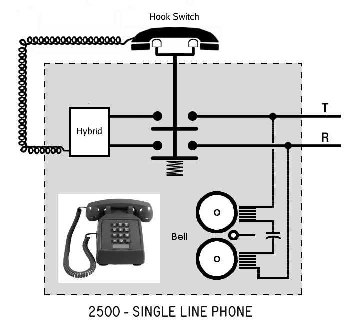
To achieve these design goals, Bell Labs started with the successful single line model
500 phone, with its voice hybrid, handset, dial, and bell. To support multiple lines,
electromechanical "Line Select" buttons were added below the dial to let the user select
any one of 5 lines. Lamps under each button light up to show the status of each line:
"off" - the line is Idle
"on" - the line is In Use
"flashing" - the line has an Incoming Call
"winking" - the line is on Hold
This resulted in a series of 1a2 compatible multiline phones such as the model 564,
a 5 line 6 button rotary dial set.
The phone is capable of selecting phone lines by itself without the assistance of
other equipment; the electromechanical Line Select switches do all the line switching
internally. This allows the phones to minimally operate even during a power outage
via the CO's battery operated equipment.
But to support calls on Hold, status lights and intercom lines, external equipment is
necessary, which is housed in the "KSU", or "Key System Unit".
In the original Bell System designs, the KSU is an industrial equipment box usually
only seen by phone installers, locked away in equipment rooms. At its smallest, roughly
the size of a large shoe box, and about as heavy as a bag of sand, these small KSU's
often nicknamed "shoe boxes" could manage 4 lines, and with some extra equipment,
dialable intercom.
Larger KSUs that handled more lines could fill entire walls, the power supplies alone
could be the size of small air conditioners.
The KSU was typically located where the phone lines entered the building; for small
systems usually in a "phone closet" or basement space, or for larger systems, a
dedicated "phone room".
Separate 25 pair cables ran from the KSU to each phone set, allowing the KSU to have
control of all 50 conductors to each extension. Indeed, many of the conductors were
common between the sets, and only a few signals needed to be unique for each phone set.
The KSU contained various PCB boards, power supplies, punch blocks, and circuitry to
manage these extra functions that the phone sets themselves could not handle.
The smallest systems could manage at least 4 telco lines, and with some extra equipment,
supported intercoms with dialable extensions.
The systems were designed to be flexible, allowing for customization and interfacing to
other equipment, such as gate openers, public address sytems, etc. Extensive use of punch
blocks and screw terminal boards in the equipment allowed field rewiring by installers
for such special cases.
The Seriss KSU is a modernized version of these old KSU boxes, achieving the goals
of the original design, but leveraging the benefits of modern components to keep the
KSU small and light, and as simple to connect up and use as possible for common small
business system use cases.
Such modernization was not pursued by the Bell System, because by the time microprocessors
became ubiquitous in the late 1970's/early 1980's, they revolutionized telecommunications.
Newer systems that leveraged microprocessors (such as ComKey 416, Horizon, and later
Merlin) quickly rendered the old 1A2 electromechanical systems obsolete. So further
development of legacy 1A2 equipment was not pursued by the phone company.
But modern phone systems can be complicated, and sometimes old technology can be
refreshed, which is the design goal of the Seriss "single board KSU".
* * *
What follows are brief technical descriptions of the different parts of a 1A2 phone
system, to give context to the circuit descriptions that follow in later sections:
1.1 - Overview of Seriss KSU Features
-------------------------------------
The Seriss KSU provides these common 1A2 features:
* Hold for both lines, all 4 extensions
* Lamp indicators:
- Blink for incoming calls (1Hz)
- On steady when in use
- Wink when on Hold (2Hz / 80% Duty)
- Off when line is idle
* Programmable ringing for incoming calls, bells and buzzers.
An external ring generator is required for bells to operate under KSU control.
* Intercom feature hardwired to Line #5 with Touch-Tone or Rotary dialing supported
* 2 KSU boards can be interlinked for a total of 4 lines / 8 Extensions
* In a power outage, phones can still be used to dial out
* Handles Disconnect Supervision (aka CPC, or Calling Party Control) signaling
if provided by CO
The intercom on Line #5 allows local intercommunication between the KSU extensions
by dialing the extension number (1 thru 4) on either a Rotary or Touch-Tone dial
to buzz any of the 4 extensions. This triggers the buzzer at that extension notifying
anyone nearby to pickup the intercom line. Dialing "0" buzzes all 4 extensions.
The system is expandable: 2 boards can be interlinked with a 30 pin ribbon cable,
supporting a total of 4 lines and 8 extensions. Intercom is expanded as well, so
dialing digits "1" through "8" buzzes the respective extension, and "0" buzzes them all.
1.2 - Overview of CO Line States
--------------------------------
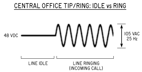
The CO (Central Office) trunk voltages vary depending on the state of the telco line:
> CO Line idle: 48 VDC (Approx.)
------------------------------
The CO provides -48 VDC across Tip/Ring when the line is idle.
When the line is idle, there should be close to zero current flow.
This relatively high DC voltage is used to detect if someone picks up the line.
Actual voltage may be lower due to physical distance from the CO.
> CO Line In Use: ~24VDC (Approx.)
--------------------------------
When the line is in use, the CO provides a "talk battery" of around 24VDC.
This voltage must be high enough to operate one or more extension phone's
voice circuits, which can operate on a variety of voltages down to even 6VDC.
Often the DC voltage is lower due to physical distance from the CO.
The bi-directional voice frequencies ride on top of the battery voltage.
> CO Line Ringing: ~105 VAC / 25 Hz
---------------------------------
When the CO wants to ring the line, it cuts 105 VAC at the ringing frequency
of around 25 Hz. A large value capacitor in common with the bell inside each phone
blocks DC current flow through the bell's coils, to prevent current flow that might
cause the CO to think the line has gone off-hook.
The KSU monitors these voltages to detect the line's state, and are described below under
the "Ring Detect" and "Line Detect" circuits.
1.3 - 1A2 Line States
---------------------
1A2 systems have the following states for each of the CO provided trunk lines:
> Line Idle - lamps are off, all extensions are on hook
> Incoming Call - the line is ringing, the line's lamp flashes at 1Hz
> Line In Use - when someone is talking on the line, the line's lamp is on steady
> Line On Hold - when someone has the line on Hold, the line's lamp winks at 2Hz
1.4 - 1A2 Phones
----------------
1A2 "Key Telephones" are a multiline phone systems that follow a convention of
simple electromechanical circuitry designed by Bell Labs as a solution for business
phone systems.
The phones are very similar to their single line counterparts; they have a single
network hybrid (voice circuit) connected to the handset, hookswitch and dial:
 Key phones differ: extra "Line Select" switches allow selecting one of multiple lines.
Lamps under each line button indicate status of the line for that button; "Off" for idle,
"On" or "Flashing" for in use. The Bell is wired to its own dedicated wire pair instead of
Tip/Ring of one of the lines, and a Buzzer is also wired to a dedicated wire pair, so both
can be controlled directly by the KSU control unit:
Key phones differ: extra "Line Select" switches allow selecting one of multiple lines.
Lamps under each line button indicate status of the line for that button; "Off" for idle,
"On" or "Flashing" for in use. The Bell is wired to its own dedicated wire pair instead of
Tip/Ring of one of the lines, and a Buzzer is also wired to a dedicated wire pair, so both
can be controlled directly by the KSU control unit:
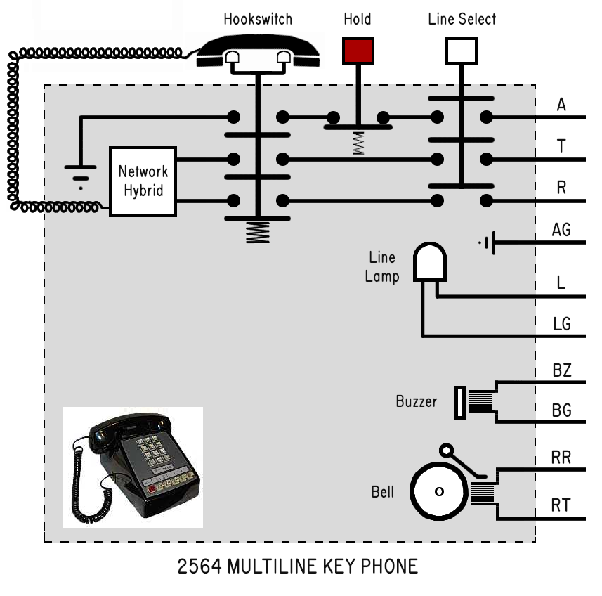 Also, there's usually a large field of terminal screws within the phone onto which the
25 pair cable breaks out, so the phone installer can reassign the wires to different purposes.
1.4.1 - 1A2 Phones: Line Select Buttons
---------------------------------------
The live Tip/Ring pairs for each CO line run directly to all the 1A2 phones
over the phones' 25 pair cables.
No switching is done at the KSU. All switching is done manually by the person
at the Line Select buttons. When a Line button is pressed, the mechanics of the
switch prevent more than one line from being selected at once.
For example, when the Line #1 button is pressed:
> All other line buttons pop up
> The A lead is connected to +12v (provided by the KSU) through both
the switchhook and "normally closed" Hold button.
> The Line #1's Tip/Ring pair is connected to the voice hybrid circuit of
the phone through the switchhook. To hear dial tone for Line #1, the button
has to be selected AND the phone must be off-hook. The Tip/Ring pairs for
the other lines are left "open".
1.4.2 - 1A2 Phones: Hold Button
-------------------------------
The Hold button is a special case; it is a spring loaded "normally closed" switch
that breaks open when pressed, interrupting the A lead signal while the button is
held down.
The mechanics of the Hold button is such that, when pressed down, the Line Select
button remains down, and pops the button up when the Hold button is released.
The fact the A lead is opened but the line remains selected when the Hold key
is pressed down is an important design in how the KSU recognizes which line
is being put on Hold.
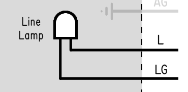
1.4.3 - 1A2 Phones: Lamps
-------------------------
The lamp below each line button are directly controlled by the KSU over dedicated
wire pair in the 25 pair phone cable. The lamps are 10 VAC incandescent bulbs
(Sylvania type 51A) that in the case of the Seriss KSU are operated at 12 VDC.
At this voltage, each lamp draws around 40mA.
The KSU controls whether the lamps should be on or flashing or off. The lamps
are not connected to other circuitry in the phones. So like the Bells and Buzzer,
are simply directly connected straight through to the KSU.
Also, there's usually a large field of terminal screws within the phone onto which the
25 pair cable breaks out, so the phone installer can reassign the wires to different purposes.
1.4.1 - 1A2 Phones: Line Select Buttons
---------------------------------------
The live Tip/Ring pairs for each CO line run directly to all the 1A2 phones
over the phones' 25 pair cables.
No switching is done at the KSU. All switching is done manually by the person
at the Line Select buttons. When a Line button is pressed, the mechanics of the
switch prevent more than one line from being selected at once.
For example, when the Line #1 button is pressed:
> All other line buttons pop up
> The A lead is connected to +12v (provided by the KSU) through both
the switchhook and "normally closed" Hold button.
> The Line #1's Tip/Ring pair is connected to the voice hybrid circuit of
the phone through the switchhook. To hear dial tone for Line #1, the button
has to be selected AND the phone must be off-hook. The Tip/Ring pairs for
the other lines are left "open".
1.4.2 - 1A2 Phones: Hold Button
-------------------------------
The Hold button is a special case; it is a spring loaded "normally closed" switch
that breaks open when pressed, interrupting the A lead signal while the button is
held down.
The mechanics of the Hold button is such that, when pressed down, the Line Select
button remains down, and pops the button up when the Hold button is released.
The fact the A lead is opened but the line remains selected when the Hold key
is pressed down is an important design in how the KSU recognizes which line
is being put on Hold.
1.4.3 - 1A2 Phones: Lamps
-------------------------
The lamp below each line button are directly controlled by the KSU over dedicated
wire pair in the 25 pair phone cable. The lamps are 10 VAC incandescent bulbs
(Sylvania type 51A) that in the case of the Seriss KSU are operated at 12 VDC.
At this voltage, each lamp draws around 40mA.
The KSU controls whether the lamps should be on or flashing or off. The lamps
are not connected to other circuitry in the phones. So like the Bells and Buzzer,
are simply directly connected straight through to the KSU.
 1.4.4 - 1A2 Phones: 25 Pair Cable / Connectors
----------------------------------------------
25 pair (50 conductor) cables are used instead of a the single wire pair used by
single line phones to manage the multiple lines and related signals for each line.
These cables terminate to a 50 conductor "Amphenol" connector following the
25 pair color code standard. The signals follow a general pattern for the first
5 lines, starting at the top of the connector (Pin #1).
Refer to "25 Pair Cable" in Section 3 which goes into the electrical detail of
1A2 signal assignments over 25 pair cables.
2.0 - Seriss KSU Board Layout
-----------------------------
The board has discrete component sections for modularity, which helps in comprehension
of the electrical circuit description in Section 3.
Here's a subsection index, with details to follow:
2.1 - Line Sections
* "LINE 1" - Handles Line #1's Line Detect and Ring Detect, Hold function
* "LINE 2" - Handles Line #2's Line Detect and Ring Detect, Hold function
* "CPU LOGIC" - The CPU handling line functions (interrupter, lamps, ringing..)
and detection of the A lead for Line #1 (A1) and Line #2 (A2)
2.2 - Intercom Sections
* "INTERCOM DIALING" - Handles detecting dialing on Intercom Line #5
* "ICM VOICE BATT" - Provides voice battery for Intercom Line #5
2.3 - Ringing / Buzzing Sections
* "BUZZERS" - Components that drive the buzzers
* "LINE RINGING" - Handles Line #1 and #2 ringing control xstr and relays
* "BUZZ CALL" - Handles programming incoming calls to buzz
* "BELL CALL" - Handles programming incoming calls to ring bells
* "RING GENERATOR" - The ring generator input connectors
2.4 - Miscellaneous
* "EXT 1-4" - The amphenol connectors for the phone extensions
* "INTERLINK" - The interlink jumpers JP3 and JP4, and interlink ribbon connector
2.5 - Firmware
* Timer class
* Interrupter class
* Debounce filter class
* Interlink bidirectional 1-bit communications
* PWM for 60Hz signal generation
Keeping the descriptions of each section brief:
2.1 - Line Sections
-------------------
The LINE 1 and LINE 2 sections are the same circuit for interacting
with the CO telephone lines directly:
* Ring Detect using resistors R6, capacitor C1, and optocoupler IC1
* Line Detect using resistor R7 and optocoupler IC2.
* The Hold circuit uses relay K1 and the Hold resistor R1.
* The Line's lamps are driven by the IRF-9530 power transistor Q1
and transistion dampening resistors R2 and R4.
The CPU LOGIC section uses:
* CPU1 PIC chip (IC8) which monitors the state of Line #1 + #2,
controlling lamps, buzzers, and ringing.
* ULN2803 (IC7) which acts as an output amplifier/inverter.
* The 5.6K resistor network RN1 is used for signal pull-ups and current limiting.
* The A lead detecting optocouplers:
- A1 (IC5) detects the A lead signal from the phone extensions for Line #1
- A2 (IC6) detects the A lead signal from the phone extensions for Line #2
2.2 - Intercom Sections
-----------------------
The INTERCOM DIALING section uses:
* A DTMF decoder (IC9) to handle decoding intercom Touch-Tone dialing
* An optocoupler (IC11) to handle intercom Rotary dialing
* CPU2 (IC10) which parses intercom dialed digits, and drives buzzers for
intercom dialing via the ULN2803 (IC10) signal amplifier, and current
limit resistors (RN2) for the base inputs to the TIP125 power transistors
Q7 - Q10.
The ICM VOICE BATT section provides "voice battery" for Intercom Line #5
voice path using the pair of 1 watt resistors R15 and R16.
2.3 - Ringing / Buzzing Sections
--------------------------------
The BUZZERS section includes the TIP125 PNP bipolar power transistors that
directly drive the phone buzzers. When CPU2 wants to buzz a buzzer, it drives
a +5v 60Hz signal to the appropriate ULN2803 gate, whose open collector output
drives the base of the TIP125 power transistors through one of the 10K
current limiting resistors in resistor network RN2. The negative logic
60Hz output of the ULN2803 (IC12)'s open collector outputs is logically OR'ed
with the BUZZ RING circuit's negative logic 60Hz outputs to allow either
"INTERCOM DIALING" or "BUZZ RING" circuits to control the extension buzzers.
The LINE RINGING section is comprised of:
* A TIP32 power transistor controlled by CPU1 that provides 12v during
the ring cycle to power 12v ring generators, or can operate an external
relay to control an external AC powered ring generator.
* Two relays K3 and K4 for Line #1 and #2 respectively turn "on" for each
ring burst in the KSU generated cadence when an incoming call is detected.
The BUZZ CALL and BELL CALL sections each consist of:
* DIP switches to provide programming which extensions will ring or buzz
during incoming calls on Line #1 or Line #2.
* A Diode matrix to prevent back currents through the DIP switches
The RING GENERATOR section contains two input connectors JP5 and CN4
for externally provided ring generators:
- JP5 provides connection of PowerDSINE 12volt ring generators.
- CN4 provides connection of all other ring generators such as the
Western Electric 118a, TelLabs 8101, etc.
2.4 - Miscellaneous
-------------------
The EXT 1-4 sections are the 4 amphenol connectors for the 1A2 extensions.
The INTERLINK section allows two KSU boards to be combined to manage
4 lines and 8 extension phones; one board must be configured as the PRIMARY,
the other as the SECONDARY. The headers of either JP3 or JP4 must be jumpered
with shunts to configure a PRIMARY or SECONDARY board respectively.
The two boards are interconnected by header CN9 on each board with a 30 pin
ribbon cable.
2.5 - Firmware
--------------
The firmware implements several 'classes' (in pure C code) that handle
specific features in a modular way:
* Timer class: defined in the source file "TimerMsecs.h",
and implements an up counting, self-resetting millisecond timer
that is driven by the main loop.
* Interrupter class: defined in the source file "Interrupter.h",
and emulates the old electromechanical "interrupter" that generates
the timing for ringing and lamp flashing/winking signals.
* Debounce filter class: defined in the source file "Debounce.h",
and takes a constantly updated logical input signal (0 or 1) and removes
digital noise and adds hysteresis, rejecting noise spikes to give a more
noise-free logical output. Like switch debouncing in electronics, provides
flexible high and low thresholds as well as dampening to prevent quick
transitions.
* Interlink bidirectional 1-bit communications is how two separate boards
inter-communicate:
> The PRIMARY board sends regular updates of its interrupter outputs
to the SECONDARY board as boolean (0 or 1) values, keeping the two
boards in sync:
* Interrupter Ring Relay output: 1 if "on", 0 if "off"
* Interrupter Ring Flash output: 1 if lamp "on", 0 if lamp "off"
* Interrupter Hold Flash output: 1 if lamp "on", 0 if lamp "off"
* PRIMARY board CPU Status LED state: 1 if LED on, 0 if LED off
> The SECONDARY board replies with status information of its own:
* Any lines ringing? 1 if so, 0 if not
* Any lines on hold? 1 if so, 0 if not
When any of the SECONDARY's lines are ringing or on hold, the PRIMARY
board knows to run the interrupter so it can provide synchronized
signals for Ring Relay, Ring Flash and Hold Flash.
The implementation details of the bidirectional communication are currently
defined in the comments of the "1a2-pic-cpu1-firmware.c" source code; look
for the section "Interlink Data Xmit/Recv". TBD: This description should
eventually be consolidated into "README-interlink.html".
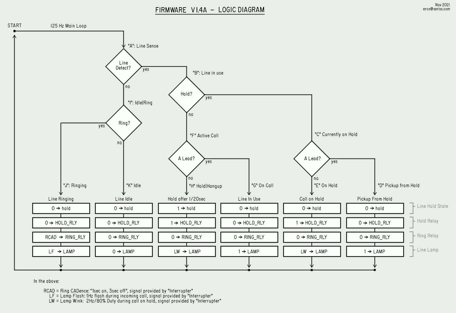
CPU1 also uses a state machine for the CO lines in the following flow char/logic diagram:
1.4.4 - 1A2 Phones: 25 Pair Cable / Connectors
----------------------------------------------
25 pair (50 conductor) cables are used instead of a the single wire pair used by
single line phones to manage the multiple lines and related signals for each line.
These cables terminate to a 50 conductor "Amphenol" connector following the
25 pair color code standard. The signals follow a general pattern for the first
5 lines, starting at the top of the connector (Pin #1).
Refer to "25 Pair Cable" in Section 3 which goes into the electrical detail of
1A2 signal assignments over 25 pair cables.
2.0 - Seriss KSU Board Layout
-----------------------------
The board has discrete component sections for modularity, which helps in comprehension
of the electrical circuit description in Section 3.
Here's a subsection index, with details to follow:
2.1 - Line Sections
* "LINE 1" - Handles Line #1's Line Detect and Ring Detect, Hold function
* "LINE 2" - Handles Line #2's Line Detect and Ring Detect, Hold function
* "CPU LOGIC" - The CPU handling line functions (interrupter, lamps, ringing..)
and detection of the A lead for Line #1 (A1) and Line #2 (A2)
2.2 - Intercom Sections
* "INTERCOM DIALING" - Handles detecting dialing on Intercom Line #5
* "ICM VOICE BATT" - Provides voice battery for Intercom Line #5
2.3 - Ringing / Buzzing Sections
* "BUZZERS" - Components that drive the buzzers
* "LINE RINGING" - Handles Line #1 and #2 ringing control xstr and relays
* "BUZZ CALL" - Handles programming incoming calls to buzz
* "BELL CALL" - Handles programming incoming calls to ring bells
* "RING GENERATOR" - The ring generator input connectors
2.4 - Miscellaneous
* "EXT 1-4" - The amphenol connectors for the phone extensions
* "INTERLINK" - The interlink jumpers JP3 and JP4, and interlink ribbon connector
2.5 - Firmware
* Timer class
* Interrupter class
* Debounce filter class
* Interlink bidirectional 1-bit communications
* PWM for 60Hz signal generation
Keeping the descriptions of each section brief:
2.1 - Line Sections
-------------------
The LINE 1 and LINE 2 sections are the same circuit for interacting
with the CO telephone lines directly:
* Ring Detect using resistors R6, capacitor C1, and optocoupler IC1
* Line Detect using resistor R7 and optocoupler IC2.
* The Hold circuit uses relay K1 and the Hold resistor R1.
* The Line's lamps are driven by the IRF-9530 power transistor Q1
and transistion dampening resistors R2 and R4.
The CPU LOGIC section uses:
* CPU1 PIC chip (IC8) which monitors the state of Line #1 + #2,
controlling lamps, buzzers, and ringing.
* ULN2803 (IC7) which acts as an output amplifier/inverter.
* The 5.6K resistor network RN1 is used for signal pull-ups and current limiting.
* The A lead detecting optocouplers:
- A1 (IC5) detects the A lead signal from the phone extensions for Line #1
- A2 (IC6) detects the A lead signal from the phone extensions for Line #2
2.2 - Intercom Sections
-----------------------
The INTERCOM DIALING section uses:
* A DTMF decoder (IC9) to handle decoding intercom Touch-Tone dialing
* An optocoupler (IC11) to handle intercom Rotary dialing
* CPU2 (IC10) which parses intercom dialed digits, and drives buzzers for
intercom dialing via the ULN2803 (IC10) signal amplifier, and current
limit resistors (RN2) for the base inputs to the TIP125 power transistors
Q7 - Q10.
The ICM VOICE BATT section provides "voice battery" for Intercom Line #5
voice path using the pair of 1 watt resistors R15 and R16.
2.3 - Ringing / Buzzing Sections
--------------------------------
The BUZZERS section includes the TIP125 PNP bipolar power transistors that
directly drive the phone buzzers. When CPU2 wants to buzz a buzzer, it drives
a +5v 60Hz signal to the appropriate ULN2803 gate, whose open collector output
drives the base of the TIP125 power transistors through one of the 10K
current limiting resistors in resistor network RN2. The negative logic
60Hz output of the ULN2803 (IC12)'s open collector outputs is logically OR'ed
with the BUZZ RING circuit's negative logic 60Hz outputs to allow either
"INTERCOM DIALING" or "BUZZ RING" circuits to control the extension buzzers.
The LINE RINGING section is comprised of:
* A TIP32 power transistor controlled by CPU1 that provides 12v during
the ring cycle to power 12v ring generators, or can operate an external
relay to control an external AC powered ring generator.
* Two relays K3 and K4 for Line #1 and #2 respectively turn "on" for each
ring burst in the KSU generated cadence when an incoming call is detected.
The BUZZ CALL and BELL CALL sections each consist of:
* DIP switches to provide programming which extensions will ring or buzz
during incoming calls on Line #1 or Line #2.
* A Diode matrix to prevent back currents through the DIP switches
The RING GENERATOR section contains two input connectors JP5 and CN4
for externally provided ring generators:
- JP5 provides connection of PowerDSINE 12volt ring generators.
- CN4 provides connection of all other ring generators such as the
Western Electric 118a, TelLabs 8101, etc.
2.4 - Miscellaneous
-------------------
The EXT 1-4 sections are the 4 amphenol connectors for the 1A2 extensions.
The INTERLINK section allows two KSU boards to be combined to manage
4 lines and 8 extension phones; one board must be configured as the PRIMARY,
the other as the SECONDARY. The headers of either JP3 or JP4 must be jumpered
with shunts to configure a PRIMARY or SECONDARY board respectively.
The two boards are interconnected by header CN9 on each board with a 30 pin
ribbon cable.
2.5 - Firmware
--------------
The firmware implements several 'classes' (in pure C code) that handle
specific features in a modular way:
* Timer class: defined in the source file "TimerMsecs.h",
and implements an up counting, self-resetting millisecond timer
that is driven by the main loop.
* Interrupter class: defined in the source file "Interrupter.h",
and emulates the old electromechanical "interrupter" that generates
the timing for ringing and lamp flashing/winking signals.
* Debounce filter class: defined in the source file "Debounce.h",
and takes a constantly updated logical input signal (0 or 1) and removes
digital noise and adds hysteresis, rejecting noise spikes to give a more
noise-free logical output. Like switch debouncing in electronics, provides
flexible high and low thresholds as well as dampening to prevent quick
transitions.
* Interlink bidirectional 1-bit communications is how two separate boards
inter-communicate:
> The PRIMARY board sends regular updates of its interrupter outputs
to the SECONDARY board as boolean (0 or 1) values, keeping the two
boards in sync:
* Interrupter Ring Relay output: 1 if "on", 0 if "off"
* Interrupter Ring Flash output: 1 if lamp "on", 0 if lamp "off"
* Interrupter Hold Flash output: 1 if lamp "on", 0 if lamp "off"
* PRIMARY board CPU Status LED state: 1 if LED on, 0 if LED off
> The SECONDARY board replies with status information of its own:
* Any lines ringing? 1 if so, 0 if not
* Any lines on hold? 1 if so, 0 if not
When any of the SECONDARY's lines are ringing or on hold, the PRIMARY
board knows to run the interrupter so it can provide synchronized
signals for Ring Relay, Ring Flash and Hold Flash.
The implementation details of the bidirectional communication are currently
defined in the comments of the "1a2-pic-cpu1-firmware.c" source code; look
for the section "Interlink Data Xmit/Recv". TBD: This description should
eventually be consolidated into "README-interlink.html".
CPU1 also uses a state machine for the CO lines in the following flow char/logic diagram:
 (click to view full image)
The letter markers in this diagram are referenced in the state machine source code
to identify each specific state and its handler code.
3.0 - KSU Electrical Description
--------------------------------
This section covers the operation of the KSU circuits in detail, and cover
electrical design considerations.
Simplified diagrams are included with the text below, but the text meant to augment
the KSU schematics. Also, refer to the PCB board layout for the actual board wiring.
In the following sections:
* 3.1 - CO Line Handling: Incoming calls, putting calls on Hold, retrieving calls.
> 3.1.1 - Ring Detect - Detect ringing on the CO line during an incoming call
> 3.1.2 - Line Detect - Detect whether the CO line is "in use" or "idle"
> 3.1.3 - A1/A2 Detect - Detects the line's A lead signal from the phone extensions
* 3.2 - Ring Handling
> 3.2.x - Incoming call: bell ringing
> 3.2.x - Incoming call: buzz ringing
* 3.4 - Intercom - Dialing and voice circuit
* 3.5 - Interlink jumpers and cable
* 3.6 - 25 Pair Cable and Amphenol Connector wiring
<<<
<<< I YAM HERE
<<<
3.1 - CO Line Handling
----------------------
The CO lines are passed directly through the KSU to the line extensions. The Tip/Ring
pair from the CO pass through optocouplers IC1 and IC2 to sense, but not impede the
telco's signals.
Since the Line #1 circuit is exactly the same as Line #2's, for simplicity only Line
#1's components will be referred to.
There's two things the KSU must sense from the CO line, and one from the phone extensions,
each uses separate circuits to do so:
> Ring Detect - Detect ringing on the CO line during an incoming call
> Line Detect - Detect whether the CO line is "in use" or "idle"
> A1/A2 Detect - Detects the line's A lead signal from the phone extensions
All of these circuits use LDA-110 "AC input" optocouplers, and effectively isolate the
CO signals from the KSU's own. The AC inputs on the optocoupler are back-to-back LEDs,
and have darlington transistors with open collector outputs. H11AA1 optocouplers are
equivalent to the LDA-110, and can therefore be used interchangeably.
An in-depth description of each of these circuits:
3.1.1 - "Ring Detect"
---------------------
When the CO line is idle, it rests at 48 VDC. When there's an incoming
call, the CO cuts in a 105 VAC/25 Hz ring voltage with sufficient power
to drive several common electromechanical bells:
(click to view full image)
The letter markers in this diagram are referenced in the state machine source code
to identify each specific state and its handler code.
3.0 - KSU Electrical Description
--------------------------------
This section covers the operation of the KSU circuits in detail, and cover
electrical design considerations.
Simplified diagrams are included with the text below, but the text meant to augment
the KSU schematics. Also, refer to the PCB board layout for the actual board wiring.
In the following sections:
* 3.1 - CO Line Handling: Incoming calls, putting calls on Hold, retrieving calls.
> 3.1.1 - Ring Detect - Detect ringing on the CO line during an incoming call
> 3.1.2 - Line Detect - Detect whether the CO line is "in use" or "idle"
> 3.1.3 - A1/A2 Detect - Detects the line's A lead signal from the phone extensions
* 3.2 - Ring Handling
> 3.2.x - Incoming call: bell ringing
> 3.2.x - Incoming call: buzz ringing
* 3.4 - Intercom - Dialing and voice circuit
* 3.5 - Interlink jumpers and cable
* 3.6 - 25 Pair Cable and Amphenol Connector wiring
<<<
<<< I YAM HERE
<<<
3.1 - CO Line Handling
----------------------
The CO lines are passed directly through the KSU to the line extensions. The Tip/Ring
pair from the CO pass through optocouplers IC1 and IC2 to sense, but not impede the
telco's signals.
Since the Line #1 circuit is exactly the same as Line #2's, for simplicity only Line
#1's components will be referred to.
There's two things the KSU must sense from the CO line, and one from the phone extensions,
each uses separate circuits to do so:
> Ring Detect - Detect ringing on the CO line during an incoming call
> Line Detect - Detect whether the CO line is "in use" or "idle"
> A1/A2 Detect - Detects the line's A lead signal from the phone extensions
All of these circuits use LDA-110 "AC input" optocouplers, and effectively isolate the
CO signals from the KSU's own. The AC inputs on the optocoupler are back-to-back LEDs,
and have darlington transistors with open collector outputs. H11AA1 optocouplers are
equivalent to the LDA-110, and can therefore be used interchangeably.
An in-depth description of each of these circuits:
3.1.1 - "Ring Detect"
---------------------
When the CO line is idle, it rests at 48 VDC. When there's an incoming
call, the CO cuts in a 105 VAC/25 Hz ring voltage with sufficient power
to drive several common electromechanical bells:
 To detect ringing, the LDA-110 optocoupler IC1 is connected across
the CO line's Tip and Ring signals to detect AC ring voltage:
To detect ringing, the LDA-110 optocoupler IC1 is connected across
the CO line's Tip and Ring signals to detect AC ring voltage:
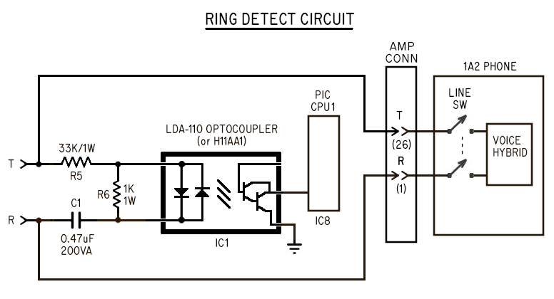 In the above, the 33K resistor (R5) and 0.47uF capacitor (C1) together
form a DC blocking R/C filter to prevent the optocoupler turning on for any
DC voltage on the line. These components also block high voice frequencies,
passing only the relatively low frequency/high voltage 105 VAC/25Hz ring
voltage sufficient to drive the optocoupler through the 33K resistor.
A parallel 1K resistor (R6) across the optocoupler's inputs further
desensitizes the optocoupler from low voltage transients to prevent
false ring triggers.
The optocoupler's output drives CPU1 input port RA5. When idle, the
optocoupler's open collector output floats, driven high to +5v by
the CPU1 input port's internal pull up resistors (configured in firmware)
causing it to see logic "1" when the line is not ringing.
When ringing is present, the optocoupler's output is forced to ground,
causing CPU1 to see RA5 as logic "0".
NOTE: The IC1 optocoupler briefly turns off during all zero crossings of
the CO ring voltage AC wave, causing CPU1 to actually see hi/low transitions
during ringing at double the AC ring frequency.
In the above, the 33K resistor (R5) and 0.47uF capacitor (C1) together
form a DC blocking R/C filter to prevent the optocoupler turning on for any
DC voltage on the line. These components also block high voice frequencies,
passing only the relatively low frequency/high voltage 105 VAC/25Hz ring
voltage sufficient to drive the optocoupler through the 33K resistor.
A parallel 1K resistor (R6) across the optocoupler's inputs further
desensitizes the optocoupler from low voltage transients to prevent
false ring triggers.
The optocoupler's output drives CPU1 input port RA5. When idle, the
optocoupler's open collector output floats, driven high to +5v by
the CPU1 input port's internal pull up resistors (configured in firmware)
causing it to see logic "1" when the line is not ringing.
When ringing is present, the optocoupler's output is forced to ground,
causing CPU1 to see RA5 as logic "0".
NOTE: The IC1 optocoupler briefly turns off during all zero crossings of
the CO ring voltage AC wave, causing CPU1 to actually see hi/low transitions
during ringing at double the AC ring frequency.
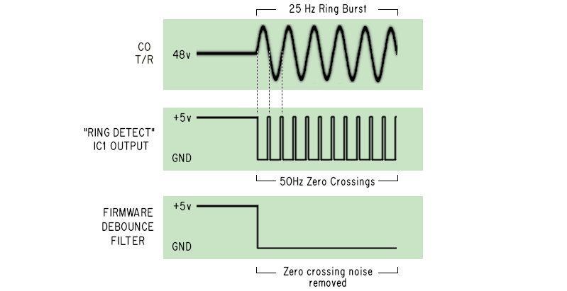 The CPU1 firmware uses a debounce filter tuned to ignore postive
and negative going spikes due to line noise, but also has the effect
of rejecting the short zero crossing pulses as "noise".
More detail on how the KSU responds to Ring Detect can be found in the
"Ring Handling" section below.
3.1.2 - "Line Detect"
---------------------
The AC input optocoupler IC2 in series with the telco's Tip/Ring pair,
detecting current flow if the line is in use or on hold.
The CPU1 firmware uses a debounce filter tuned to ignore postive
and negative going spikes due to line noise, but also has the effect
of rejecting the short zero crossing pulses as "noise".
More detail on how the KSU responds to Ring Detect can be found in the
"Ring Handling" section below.
3.1.2 - "Line Detect"
---------------------
The AC input optocoupler IC2 in series with the telco's Tip/Ring pair,
detecting current flow if the line is in use or on hold.
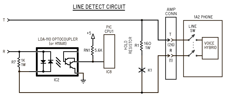 The Line Detect optocoupler is energized whenever there current flow,
which happens if one or more of the extensions is off hook with the
line selected (causing the network hybrid's voice circuit to consume power),
or current flow through the Hold resistor (if the Hold relay is energized).
Line Detect will deenergize if an extension active on the line hangs up.
It will also deenergize if the CO sends a CPC / Disconnect Supervision signal
while a call is on Hold, indicating the remote caller hung up.
Line Detect handles 3 line states:
Idle
----
When the extensions are all idle (on hook) and the line is not on Hold,
there is no current flow across Tip/Ring, causing the optocoupler to turn off.
Its open collector output floats, pulled high to +5V by one of the 5.6K
resistors in RN1, causing CPU1 to see the output of the optocoupler as logic 1.
In Use
------
When an extension goes off-hook, CO's line current travels through the offhook
extension's voice circuit (network hybrid), and that current flow turns on the
Line Detect optocoupler, grounding its output, causing CPU1 to see the output
of the optocoupler as logic 0.
On Hold
--------
When the line is on Hold, resistor R1 is shunted across Tip and Ring (via the
Hold relay K1). As with the CO, this keeps Line Detect seeing current flow.
Like the "In Use" state, the optocoupler is on with its output grounded,
causing CPU1 to see the output of the optocoupler as logic 0.
Since CPU1 controls whether a call is on Hold or not, it doesn't need to
use Line Detect to know the line is on Hold, but does use Line Detect
to discriminate between a "hang up" and when the Hold button is pressed.
CPU1 using a combination of the Line Detect and A Lead Detect signals
to make this determination. For more info, see "Hold Detect")
CPU1 uses the Line Detect signal to manage the extension lamps and to detect the
difference between a call being hung up or put on Hold.
This circuit is the same for Line #1 and Line #2.
3.1.3 - "A1/A2 Detect": A Lead Detection
----------------------------------------
The A lead signal for Line #1 and #2 is detected by optocouplers A1 (IC5)
and A2 (IC6) respectively.
When a line is selected and off-hook, the signal provides +12 volts.
When the Hold button is pressed down, the A lead goes open.
When someone hangs up, the A lead goes open.
The A lead signal directly drives the inputs to the A1/A2 optocouplers,
current limited by 5.6K resistors in RN1.
The A1 and A2 optocoupler's outputs drive CPU1's RC5 and RC4 input
ports respectively, their open collector outputs each pulled high to
+5v by a 5.6K resistor provided by RN1.
When e.g. Line #1 is idle, A1 is deenergized, its open collector output
floats, pulled to +5v by RN1, causing CPU1 to see logic "1" on port RC5.
When someone picks up Line #1 by having selecting the line and going off-hook,
+12v is provided to the input of the A1 optocoupler causing it to energize.
A1's open collector output pulls to ground, causing CPU1 to see logic "0"
on port RC5 when the line is in use.
The optocoupler acts as both an isolator from the +5v circuit, and as a noise
reducer for the A lead signal carried by potentially long 25 pair cables. Each
extension can easily be 100 feet away, potentially pickup up RF transients.
Debouncing filters in firmware further prevent false triggers of the A lead.
Together these 3 signals, "Ring Detect", "Line Detect", and "A1 Detect" are used
by the KSU to monitor and control the state of each of the CO trunk lines.
3.2 - Ring Handling
-------------------
This covers the electrical details of how ringing is handled for Bells and Buzzers.
For simplicity, we'll refer only to Line #1's components, since the circuits
for Line #1 and Line #2 are exactly the same.
As previously described in the "Ring Detect" circuit section, when a line is
ringing, CPU1 sees a logic "0" on input port RA5.
The firmware then transitions the line state to "Ringing" (see Firmware Logic Diagram),
causing the following behavior in the KSU:
> RING CYCLE TIMER START
A 6 second 'ring timer' for the line is started, and if another ring from the
CO occurs, the interrupter continues running for another 6 seconds, keeping
the line lamps flashing and the bell ringing.
> INTERRUPTER START
The firmware emulated "Interrupter" is started( if not already running
due to other lines ringing on Hold), generating the Ring Flash (aka. LF),
Hold Wink (aka. LW), and Ring Relay signals.
For an electrical description, see "Firmware -> Interrupter" below.
> LAMP FLASHING
The Line #1 lamp begins flashing at 1Hz to indicate the incoming call
for that line. The 1Hz signal is provided by the firmware interrupter's
"Ring Flash" output.
For an electrical description, see "Phone Outputs -> Line Lamps"
> RING RELAY: BELL + BUZZER RINGING
The KSU will begin operating the L1 RING relay (K3) at the ring cadence
(1 sec on, 3 sec off), directing ring/buzz signals that operate
bells programmed to ring by SW2 in the BELL CALL section, and
buzzers programmed to buzz by SW1 in the BUZZ CALL section.
For an electrical description, see "Phone Outputs -> Bell Ring"
and "Phone Outputs -> Buzz Ring".
> RING GENERATOR POWER
The TIP32 transistor Q4 will be turned on and will remain energized for
the entire ring cycle (even between rings) to power any external ring generator.
The output of this transistor can either directly power an external PowerDSINE
ring generator attached to JP5, or any 12v control circuitry connected to
Pins #1 and #2 of "EXT RING GEN" connector CN4.
If someone answers the call at an extension, the firmware sees "A1 Detect" and
"Line Detect" optocouplers energized, causing the firmware to change the Line #1
state from "Ringing" to "In Use". This stops the line's 6 second "ring timer",
and forces Line #1's lamp to the "steady on" state, indicating the line is in use.
If no one answers the call and the remote caller hangs up, the CO stops sending
ring bursts. Without new "Ring Detect" signals to retrigger it, the 6 second ring
timer expires, which effectively:
> Turns off TIP32 transistor (Q4), shutting down any external ring generator operating
from its power output.
> The L1 RING relay stops operating at the ring cadence, silencing all ringing for Line #1
> The L1_LAMP output from CPU1 turns off, turning off the IRF9530 lamp transistor Q1
> Changes the firmware state for Line #1 from "Ringing" to "Idle"
Line In Use / Call In Progress
------------------------------
When the line is in use during a voice call, the CO supplies ~12 volts DC,
with analog voice frequencies riding the DC signal. (Voltage varies depending
on distance from the CO's voice battery)
This state is ignored by the Ring Detect circuit due to the DC blocking
R5 and C1 configuration, and the desensitizing resistor R6.
Ring Handling: Overview
-----------------------
Once the ring signal is detected with the above circuit, the firmware in CPU1
controls what happens next.
When CPU1 detects ringing, it starts a 6 second "ring timer", and starts the
line's lamps flashing at a 1Hz rate, and turns on the coil of the L1 RING relay
(K3) by way of ULN2803 (IC7) at the KSU's ring cadence of 1 sec ring / 3 sec silence.
To keep the lamp flashing during the silence between ring bursts from the CO, the
KSU's 6 second "ring timer" is used to keep the KSU in the "ringing" state.
It is assumed the spacing between the CO's ring bursts is less than 6 seconds,
so that the "ring timer" is restarted before it expires, keeping the lamps
flashing continuously during the entire incoming call.
If no one answers the line and the remote caller hangs up, the CO will stop sending
ring bursts, allowing the 6 second "ring timer" to expire, which will stop
the lamps flashing and stop the ring cadence generated by the KSU.
Ring Handling: Circuit
----------------------
During ringing, the CPU LOGIC circuit does three things:
> Flashes the line's lamps at 1Hz via the FET power transistor (Q1).
> Energizes the ring relay (K3) at the ring cadence (1 sec on, 3 sec off).
> Energizes the bipolar power transistor Q4 for the entire ring cycle, which is used
to turn on any external ring generator during ringing
To drive the line lamps, CPU1 pulls the L1_LAMP signal high, which energizes a gate
in the ULN2803 (IC7), which pulls the output to ground, turning on the IRF9530 FET
power transistor Q1, which in turn supplies +12 VDC to the line's lamp signal on all
the extensions.
To energize the ring relay, CPU1 pulls the L1_RING_RLY signal high, turning on a gate
in the ULN2803 (IC7), which pulls the output to ground, turning on the TIP32 bipolar
power transistor Q4, which outputs +12 VDC to pin #1 on CN4, and pin #3 on JP5. This
signal can be used to either directly drive a 12 volt ring generator (e.g. PowerDSINE),
or drive an external relay or other switching equipment to energize an AC powered ring
generator, so that the ring generator is energized only during ringing.
When the ring relay is energized, it switches the locally generated ring generator's
output to the phone extension's bells via the BELL CALL diode matrix (D12 thru D19)
and the extension ring programming switches at SW2, described in more detail in the
"Bell Call" section below.
The ring relay also passes the BUZZ_60HZ signal generated by a hardware PWM in
the PIC to operate the extension's buzzers via the BUZZ CALL diode matrix (IC13)
and the extension buzz programming switches at SW1. This is described in more detail
in the "Buzz Call" section below.
This circuit is the same for Line #1 and Line #2.
<<<
<<<-- I YAM HERE: INSERT OTHER SECTIONS 3.3, 3.4, 3.5.
<<<
3.6 - 25 Pair Cable and Amphenol Connector wiring
-------------------------------------------------
The Ampenol connector for 25 pair cables has two columns of 25 pins directly opposite
each other, for a total of 50 conductors. Each twisted wire pair connected to a pair
of opposite pins in each row.
Example: For the White/Blue pair:
> The White/Blue conductor connects to Pin #26
> The Blue/White conductor connects to Pin #1
Pin #1 and #26 are directly opposite each other on the Amphenol connector:
> Pin #1 in the left column
> Pin #26 in the right column
<<<
<<< I YAM HERE: This section could use some custom Amphenol color wiring diagrams
<<< that clarify how wire pairs are connected to each row on the connector.
<<<
1A2 model phones generally follow similar wiring, especially for 5 line phones.
Refer to the each phone model's schematics for specific wiring, which can be found in
the Bell System Practices (BSP's). Some common phone models:
Description Phone Model BSP Document Number
----------- --------------- -------------------------------------
9 Line Desk 830 + 2830 503-701-101
5 Line Wall 2851 503-601-101
5 Line Desk 564 502-541-406,407..
5 Line Desk 2565 502-543-403,405..
The wiring of the pairs follow a simple 3 pair pattern for each line:
> Tip/Ring pair
> A lead pair
> Lamp pair
Often remembered as "TRAL" (Tip/Ring,A lead, Lamp), this pattern can be found
in all 1A2 compatible phones for at least the first 5 lines. Phone sets like
the 5 line 2564, the pattern starts at the top of the amphenol connector at
Pin #1 and Pin #26 for Line #1's Tip/Ring pair, and runs down the connector,
one wire pair per row:
Pin Pair
Row Colors Left Column Right Column
---- ------ ----------- ------------ __
1 W/BL Pin #1: "Ring" Pin #26: "Tip" |
2 W/O Pin #2: A lead ground Pin #27: A lead signal |-- Line #1 pairs
3 W/G Pin #3: Lamp signal Pin #28: Lamp ground __|
__
4 W/BR Pin #4: "Ring" Pin #29: "Tip" |
5 W/S Pin #5: Spare Pin #30: A lead signal |-- Line #2 pairs
6 R/BL Pin #6: Lamp signal Pin #31: Lamp ground __|
..etc..
__
13 BK/G Pin #13: "Ring" Pin #38: "Tip" |
14 BK/BR Pin #14: Spare Pin #39: A lead signal |-- Line #5 pairs
15 BK/S Pin #15: Lamp signal Pin #40: Lamp ground __|
NOTE: The A lead signal of all lines share a common ground for Line #1 at Pin #2.
So the second conductor for the A lead signals for lines #2 through #5
are all available as spares for any custom special purpose use.
Beyond Line #5, wiring becomes unique to each phone; refer to the phone schematics.
Generally in 1A2, the following specific wire pairs are reserved for the Bells and
Buzzers, and are the signals the Seriss KSU uses:
Pair
Colors Left Side Pins Right Side Pins
------ -------------- ---------------
Y/O Pin #17: Buzzer Pin #42: Buzzer **
Y/S Pin #20: Bell Pin #45: Bell
** Some phone models use the Y/G pair (Pin #18/#43) for Buzzers.
Those phones need to have their internal wiring modified to work with
the Seriss KSU so the buzzer is attached to the Y/O pair instead.
Modifying the phone's internal wiring is standard practice, and can be
modified easily on the terminal board inside the phone set.
Aside from the above, the remaining wire pairs do not follow a specific pattern,
and some model phones have wiring variations, especially for phones with more
than 5 lines, or that have dedicated features such as supporting speakerphones.
For instance, on 9 line phones (e.g. model 2830), the first 5 lines follow the
above pattern, but the four "Spare" A lead conductors for Lines #2 through #5
are hard wired for use by the phone's A leads for Line #6, #7, #8 and #9.
Since the A lead circuits are neither sensitive to electrical noise nor cause it,
it is not imperitive they utilize dedicated twisted pairs for each signal.
Tip/Ring pairs, however, MUST use dedicated twisted pairs, as they are very
sensitive to external noise, and benefit from the inherent noise reduction
of twisted pair technology.
The Lamp pairs SHOULD use dedicated twisted pairs, as they can generate noise
while flashing, which can be picked up by the sensitive voice circuits. This is
due to current surges that occur when an incandescent is first turned on, and
can be perceived as 'clicks' on the voice circuit, which can be quite loud if
the cables are quite long.
The Seriss KSU's lamp transistor circuit prevents these lamp turn-on current
spikes by slightly slowing the FET transistor's turn-on time.
<<<
<<< I YAM HERE: Need to rework the following into the above, or continue sections
<<<
4.1.3 - CPC Detection / Disconnect Supervision
----------------------------------------------
When the CO detects the remote caller hung up, it briefly opens the Tip/Ring
circuit for about 1/2 a second to signal the KSU the call that was in progress
has been dropped by the remote.
If this happens while a line is on Hold, the 1/2 second "open" from the CO
causes the Line Detect circuit to deenergize, which CPU1 immediately recognizes
as a hangup, and takes the call out of hold, turning off the Hold Relay (K1),
turns off the line lamp, and returns the state of the line to "Idle".
This is useful in that it frees up the line for new calls. Had the CO not
sent the CPC / Disconnect Supervision signal, the KSU would keep the call
on Hold until someone noticed there was no one at the other end of the call,
and cleared the line manually by hanging up.
4.1.4 - Holding A Call
----------------------
When a call is in progress, and the person at that phone presses and releases
the Hold button, the KSU sees this and puts the call "On Hold". When CPU1
detects this, it energizes the Hold Relay (K1) which shorts a 160 ohm resistor
across Tip and Ring, holding the call. At this point the extension can hangup
without dropping the call.
While the line is "On Hold", CPU1 winks the line lamp at a 2Hz frequency
with an 80% duty cycle.
If an extension retrieves the call by going off hook with the line selected,
CPU1 detects the A lead signal and takes the call back out of Hold, and
stops winking the line lamp, returning it to a steady on state.
For more info on how the Hold button is detected, see the "Hold Detect"
section below.
Those are the CO detection circuits.
Next we look at the 1A2 phone extension's detection circuits:
4.2 Phone Inputs
----------------
1A2 phones have several inputs that are driven by the KSU's outputs:
> 4.2.1 - Tip/Ring voice circuit
> 4.2.2 - Line Lamps (Visual)
> 4.2.3 - Bell (Audible)
> 4.2.4 - Buzzer (Audible)
The CPU1 and CPU2 PIC chips control these by way of ULN2803 darlington transistor
arrays to boost the PIC chip's output current that in turn drive power transistors
(IRF9530 and TIP125) and relays to drive the actual phone equipment over the 25 pair
cables.
4.2.1 - Tip/Ring
----------------
The Tip/Ring signals are the voice path, and are essentially passed directly through
the KSU from the CO to the 1A2 extension phones. These lines only pass through
optocouplers (for sensing line states) and the Hold Relays (K1/K2) which can be
switched to put the line "On Hold".
4.2.2 - Line Lamps
------------------
The Line Lamps are 10 VAC incandescent lamps under each line button in each extension
phone. The lamp can be lit by sending 10 VAC to the lamp wire pair for the appropriate
line. Each lamp has its own wire pair on the 25 pair extension cables. [NOTE 1]
In this system the incandescent lamps in the phones are run by 12 VDC via an
IRF9530 p-channel FET power transistor. At 12v, the lamps and consume ~40mA each,
so if all 4 extensions are connected, they'll draw 160mA through the power transistor.
With interlinked boards, a total of 8 extensions would consume 320mA.
The Line Detect optocoupler is energized whenever there current flow,
which happens if one or more of the extensions is off hook with the
line selected (causing the network hybrid's voice circuit to consume power),
or current flow through the Hold resistor (if the Hold relay is energized).
Line Detect will deenergize if an extension active on the line hangs up.
It will also deenergize if the CO sends a CPC / Disconnect Supervision signal
while a call is on Hold, indicating the remote caller hung up.
Line Detect handles 3 line states:
Idle
----
When the extensions are all idle (on hook) and the line is not on Hold,
there is no current flow across Tip/Ring, causing the optocoupler to turn off.
Its open collector output floats, pulled high to +5V by one of the 5.6K
resistors in RN1, causing CPU1 to see the output of the optocoupler as logic 1.
In Use
------
When an extension goes off-hook, CO's line current travels through the offhook
extension's voice circuit (network hybrid), and that current flow turns on the
Line Detect optocoupler, grounding its output, causing CPU1 to see the output
of the optocoupler as logic 0.
On Hold
--------
When the line is on Hold, resistor R1 is shunted across Tip and Ring (via the
Hold relay K1). As with the CO, this keeps Line Detect seeing current flow.
Like the "In Use" state, the optocoupler is on with its output grounded,
causing CPU1 to see the output of the optocoupler as logic 0.
Since CPU1 controls whether a call is on Hold or not, it doesn't need to
use Line Detect to know the line is on Hold, but does use Line Detect
to discriminate between a "hang up" and when the Hold button is pressed.
CPU1 using a combination of the Line Detect and A Lead Detect signals
to make this determination. For more info, see "Hold Detect")
CPU1 uses the Line Detect signal to manage the extension lamps and to detect the
difference between a call being hung up or put on Hold.
This circuit is the same for Line #1 and Line #2.
3.1.3 - "A1/A2 Detect": A Lead Detection
----------------------------------------
The A lead signal for Line #1 and #2 is detected by optocouplers A1 (IC5)
and A2 (IC6) respectively.
When a line is selected and off-hook, the signal provides +12 volts.
When the Hold button is pressed down, the A lead goes open.
When someone hangs up, the A lead goes open.
The A lead signal directly drives the inputs to the A1/A2 optocouplers,
current limited by 5.6K resistors in RN1.
The A1 and A2 optocoupler's outputs drive CPU1's RC5 and RC4 input
ports respectively, their open collector outputs each pulled high to
+5v by a 5.6K resistor provided by RN1.
When e.g. Line #1 is idle, A1 is deenergized, its open collector output
floats, pulled to +5v by RN1, causing CPU1 to see logic "1" on port RC5.
When someone picks up Line #1 by having selecting the line and going off-hook,
+12v is provided to the input of the A1 optocoupler causing it to energize.
A1's open collector output pulls to ground, causing CPU1 to see logic "0"
on port RC5 when the line is in use.
The optocoupler acts as both an isolator from the +5v circuit, and as a noise
reducer for the A lead signal carried by potentially long 25 pair cables. Each
extension can easily be 100 feet away, potentially pickup up RF transients.
Debouncing filters in firmware further prevent false triggers of the A lead.
Together these 3 signals, "Ring Detect", "Line Detect", and "A1 Detect" are used
by the KSU to monitor and control the state of each of the CO trunk lines.
3.2 - Ring Handling
-------------------
This covers the electrical details of how ringing is handled for Bells and Buzzers.
For simplicity, we'll refer only to Line #1's components, since the circuits
for Line #1 and Line #2 are exactly the same.
As previously described in the "Ring Detect" circuit section, when a line is
ringing, CPU1 sees a logic "0" on input port RA5.
The firmware then transitions the line state to "Ringing" (see Firmware Logic Diagram),
causing the following behavior in the KSU:
> RING CYCLE TIMER START
A 6 second 'ring timer' for the line is started, and if another ring from the
CO occurs, the interrupter continues running for another 6 seconds, keeping
the line lamps flashing and the bell ringing.
> INTERRUPTER START
The firmware emulated "Interrupter" is started( if not already running
due to other lines ringing on Hold), generating the Ring Flash (aka. LF),
Hold Wink (aka. LW), and Ring Relay signals.
For an electrical description, see "Firmware -> Interrupter" below.
> LAMP FLASHING
The Line #1 lamp begins flashing at 1Hz to indicate the incoming call
for that line. The 1Hz signal is provided by the firmware interrupter's
"Ring Flash" output.
For an electrical description, see "Phone Outputs -> Line Lamps"
> RING RELAY: BELL + BUZZER RINGING
The KSU will begin operating the L1 RING relay (K3) at the ring cadence
(1 sec on, 3 sec off), directing ring/buzz signals that operate
bells programmed to ring by SW2 in the BELL CALL section, and
buzzers programmed to buzz by SW1 in the BUZZ CALL section.
For an electrical description, see "Phone Outputs -> Bell Ring"
and "Phone Outputs -> Buzz Ring".
> RING GENERATOR POWER
The TIP32 transistor Q4 will be turned on and will remain energized for
the entire ring cycle (even between rings) to power any external ring generator.
The output of this transistor can either directly power an external PowerDSINE
ring generator attached to JP5, or any 12v control circuitry connected to
Pins #1 and #2 of "EXT RING GEN" connector CN4.
If someone answers the call at an extension, the firmware sees "A1 Detect" and
"Line Detect" optocouplers energized, causing the firmware to change the Line #1
state from "Ringing" to "In Use". This stops the line's 6 second "ring timer",
and forces Line #1's lamp to the "steady on" state, indicating the line is in use.
If no one answers the call and the remote caller hangs up, the CO stops sending
ring bursts. Without new "Ring Detect" signals to retrigger it, the 6 second ring
timer expires, which effectively:
> Turns off TIP32 transistor (Q4), shutting down any external ring generator operating
from its power output.
> The L1 RING relay stops operating at the ring cadence, silencing all ringing for Line #1
> The L1_LAMP output from CPU1 turns off, turning off the IRF9530 lamp transistor Q1
> Changes the firmware state for Line #1 from "Ringing" to "Idle"
Line In Use / Call In Progress
------------------------------
When the line is in use during a voice call, the CO supplies ~12 volts DC,
with analog voice frequencies riding the DC signal. (Voltage varies depending
on distance from the CO's voice battery)
This state is ignored by the Ring Detect circuit due to the DC blocking
R5 and C1 configuration, and the desensitizing resistor R6.
Ring Handling: Overview
-----------------------
Once the ring signal is detected with the above circuit, the firmware in CPU1
controls what happens next.
When CPU1 detects ringing, it starts a 6 second "ring timer", and starts the
line's lamps flashing at a 1Hz rate, and turns on the coil of the L1 RING relay
(K3) by way of ULN2803 (IC7) at the KSU's ring cadence of 1 sec ring / 3 sec silence.
To keep the lamp flashing during the silence between ring bursts from the CO, the
KSU's 6 second "ring timer" is used to keep the KSU in the "ringing" state.
It is assumed the spacing between the CO's ring bursts is less than 6 seconds,
so that the "ring timer" is restarted before it expires, keeping the lamps
flashing continuously during the entire incoming call.
If no one answers the line and the remote caller hangs up, the CO will stop sending
ring bursts, allowing the 6 second "ring timer" to expire, which will stop
the lamps flashing and stop the ring cadence generated by the KSU.
Ring Handling: Circuit
----------------------
During ringing, the CPU LOGIC circuit does three things:
> Flashes the line's lamps at 1Hz via the FET power transistor (Q1).
> Energizes the ring relay (K3) at the ring cadence (1 sec on, 3 sec off).
> Energizes the bipolar power transistor Q4 for the entire ring cycle, which is used
to turn on any external ring generator during ringing
To drive the line lamps, CPU1 pulls the L1_LAMP signal high, which energizes a gate
in the ULN2803 (IC7), which pulls the output to ground, turning on the IRF9530 FET
power transistor Q1, which in turn supplies +12 VDC to the line's lamp signal on all
the extensions.
To energize the ring relay, CPU1 pulls the L1_RING_RLY signal high, turning on a gate
in the ULN2803 (IC7), which pulls the output to ground, turning on the TIP32 bipolar
power transistor Q4, which outputs +12 VDC to pin #1 on CN4, and pin #3 on JP5. This
signal can be used to either directly drive a 12 volt ring generator (e.g. PowerDSINE),
or drive an external relay or other switching equipment to energize an AC powered ring
generator, so that the ring generator is energized only during ringing.
When the ring relay is energized, it switches the locally generated ring generator's
output to the phone extension's bells via the BELL CALL diode matrix (D12 thru D19)
and the extension ring programming switches at SW2, described in more detail in the
"Bell Call" section below.
The ring relay also passes the BUZZ_60HZ signal generated by a hardware PWM in
the PIC to operate the extension's buzzers via the BUZZ CALL diode matrix (IC13)
and the extension buzz programming switches at SW1. This is described in more detail
in the "Buzz Call" section below.
This circuit is the same for Line #1 and Line #2.
<<<
<<<-- I YAM HERE: INSERT OTHER SECTIONS 3.3, 3.4, 3.5.
<<<
3.6 - 25 Pair Cable and Amphenol Connector wiring
-------------------------------------------------
The Ampenol connector for 25 pair cables has two columns of 25 pins directly opposite
each other, for a total of 50 conductors. Each twisted wire pair connected to a pair
of opposite pins in each row.
Example: For the White/Blue pair:
> The White/Blue conductor connects to Pin #26
> The Blue/White conductor connects to Pin #1
Pin #1 and #26 are directly opposite each other on the Amphenol connector:
> Pin #1 in the left column
> Pin #26 in the right column
<<<
<<< I YAM HERE: This section could use some custom Amphenol color wiring diagrams
<<< that clarify how wire pairs are connected to each row on the connector.
<<<
1A2 model phones generally follow similar wiring, especially for 5 line phones.
Refer to the each phone model's schematics for specific wiring, which can be found in
the Bell System Practices (BSP's). Some common phone models:
Description Phone Model BSP Document Number
----------- --------------- -------------------------------------
9 Line Desk 830 + 2830 503-701-101
5 Line Wall 2851 503-601-101
5 Line Desk 564 502-541-406,407..
5 Line Desk 2565 502-543-403,405..
The wiring of the pairs follow a simple 3 pair pattern for each line:
> Tip/Ring pair
> A lead pair
> Lamp pair
Often remembered as "TRAL" (Tip/Ring,A lead, Lamp), this pattern can be found
in all 1A2 compatible phones for at least the first 5 lines. Phone sets like
the 5 line 2564, the pattern starts at the top of the amphenol connector at
Pin #1 and Pin #26 for Line #1's Tip/Ring pair, and runs down the connector,
one wire pair per row:
Pin Pair
Row Colors Left Column Right Column
---- ------ ----------- ------------ __
1 W/BL Pin #1: "Ring" Pin #26: "Tip" |
2 W/O Pin #2: A lead ground Pin #27: A lead signal |-- Line #1 pairs
3 W/G Pin #3: Lamp signal Pin #28: Lamp ground __|
__
4 W/BR Pin #4: "Ring" Pin #29: "Tip" |
5 W/S Pin #5: Spare Pin #30: A lead signal |-- Line #2 pairs
6 R/BL Pin #6: Lamp signal Pin #31: Lamp ground __|
..etc..
__
13 BK/G Pin #13: "Ring" Pin #38: "Tip" |
14 BK/BR Pin #14: Spare Pin #39: A lead signal |-- Line #5 pairs
15 BK/S Pin #15: Lamp signal Pin #40: Lamp ground __|
NOTE: The A lead signal of all lines share a common ground for Line #1 at Pin #2.
So the second conductor for the A lead signals for lines #2 through #5
are all available as spares for any custom special purpose use.
Beyond Line #5, wiring becomes unique to each phone; refer to the phone schematics.
Generally in 1A2, the following specific wire pairs are reserved for the Bells and
Buzzers, and are the signals the Seriss KSU uses:
Pair
Colors Left Side Pins Right Side Pins
------ -------------- ---------------
Y/O Pin #17: Buzzer Pin #42: Buzzer **
Y/S Pin #20: Bell Pin #45: Bell
** Some phone models use the Y/G pair (Pin #18/#43) for Buzzers.
Those phones need to have their internal wiring modified to work with
the Seriss KSU so the buzzer is attached to the Y/O pair instead.
Modifying the phone's internal wiring is standard practice, and can be
modified easily on the terminal board inside the phone set.
Aside from the above, the remaining wire pairs do not follow a specific pattern,
and some model phones have wiring variations, especially for phones with more
than 5 lines, or that have dedicated features such as supporting speakerphones.
For instance, on 9 line phones (e.g. model 2830), the first 5 lines follow the
above pattern, but the four "Spare" A lead conductors for Lines #2 through #5
are hard wired for use by the phone's A leads for Line #6, #7, #8 and #9.
Since the A lead circuits are neither sensitive to electrical noise nor cause it,
it is not imperitive they utilize dedicated twisted pairs for each signal.
Tip/Ring pairs, however, MUST use dedicated twisted pairs, as they are very
sensitive to external noise, and benefit from the inherent noise reduction
of twisted pair technology.
The Lamp pairs SHOULD use dedicated twisted pairs, as they can generate noise
while flashing, which can be picked up by the sensitive voice circuits. This is
due to current surges that occur when an incandescent is first turned on, and
can be perceived as 'clicks' on the voice circuit, which can be quite loud if
the cables are quite long.
The Seriss KSU's lamp transistor circuit prevents these lamp turn-on current
spikes by slightly slowing the FET transistor's turn-on time.
<<<
<<< I YAM HERE: Need to rework the following into the above, or continue sections
<<<
4.1.3 - CPC Detection / Disconnect Supervision
----------------------------------------------
When the CO detects the remote caller hung up, it briefly opens the Tip/Ring
circuit for about 1/2 a second to signal the KSU the call that was in progress
has been dropped by the remote.
If this happens while a line is on Hold, the 1/2 second "open" from the CO
causes the Line Detect circuit to deenergize, which CPU1 immediately recognizes
as a hangup, and takes the call out of hold, turning off the Hold Relay (K1),
turns off the line lamp, and returns the state of the line to "Idle".
This is useful in that it frees up the line for new calls. Had the CO not
sent the CPC / Disconnect Supervision signal, the KSU would keep the call
on Hold until someone noticed there was no one at the other end of the call,
and cleared the line manually by hanging up.
4.1.4 - Holding A Call
----------------------
When a call is in progress, and the person at that phone presses and releases
the Hold button, the KSU sees this and puts the call "On Hold". When CPU1
detects this, it energizes the Hold Relay (K1) which shorts a 160 ohm resistor
across Tip and Ring, holding the call. At this point the extension can hangup
without dropping the call.
While the line is "On Hold", CPU1 winks the line lamp at a 2Hz frequency
with an 80% duty cycle.
If an extension retrieves the call by going off hook with the line selected,
CPU1 detects the A lead signal and takes the call back out of Hold, and
stops winking the line lamp, returning it to a steady on state.
For more info on how the Hold button is detected, see the "Hold Detect"
section below.
Those are the CO detection circuits.
Next we look at the 1A2 phone extension's detection circuits:
4.2 Phone Inputs
----------------
1A2 phones have several inputs that are driven by the KSU's outputs:
> 4.2.1 - Tip/Ring voice circuit
> 4.2.2 - Line Lamps (Visual)
> 4.2.3 - Bell (Audible)
> 4.2.4 - Buzzer (Audible)
The CPU1 and CPU2 PIC chips control these by way of ULN2803 darlington transistor
arrays to boost the PIC chip's output current that in turn drive power transistors
(IRF9530 and TIP125) and relays to drive the actual phone equipment over the 25 pair
cables.
4.2.1 - Tip/Ring
----------------
The Tip/Ring signals are the voice path, and are essentially passed directly through
the KSU from the CO to the 1A2 extension phones. These lines only pass through
optocouplers (for sensing line states) and the Hold Relays (K1/K2) which can be
switched to put the line "On Hold".
4.2.2 - Line Lamps
------------------
The Line Lamps are 10 VAC incandescent lamps under each line button in each extension
phone. The lamp can be lit by sending 10 VAC to the lamp wire pair for the appropriate
line. Each lamp has its own wire pair on the 25 pair extension cables. [NOTE 1]
In this system the incandescent lamps in the phones are run by 12 VDC via an
IRF9530 p-channel FET power transistor. At 12v, the lamps and consume ~40mA each,
so if all 4 extensions are connected, they'll draw 160mA through the power transistor.
With interlinked boards, a total of 8 extensions would consume 320mA.
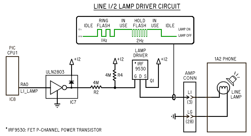 When CPU1 wants to turn on Line #1's lamps, it drives the L1_LAMP output high,
turning on a gate in the ULN2803 (IC7) which drives its open collector output low,
driving the gate input to IRF-9530 FET power transistor (Q1) through a pair of
4 megohm resistors (R2 and R4).
These high value resistors at the input gate of the FET slows its switching time,
preventing sudden current spikes when lighting the line lamps, which can cause
switching noise on the voice circuits over long 25 pair cable runs.
When CPU1 wants to turn on Line #1's lamps, it drives the L1_LAMP output high,
turning on a gate in the ULN2803 (IC7) which drives its open collector output low,
driving the gate input to IRF-9530 FET power transistor (Q1) through a pair of
4 megohm resistors (R2 and R4).
These high value resistors at the input gate of the FET slows its switching time,
preventing sudden current spikes when lighting the line lamps, which can cause
switching noise on the voice circuits over long 25 pair cable runs.
 For Line #5 (Intercom), a simple circuit controls the Line #5 lamps; the A lead
directly controls the coil for relay K5, which switches 12 VDC directly to the
line lamps.
The lamps have 4 possible states:
o Off (Idle)
o Ring flash (line ringing)
o Hold wink (line on hold)
o Continuous on (line in use)
These state changes and flash timing are all managed by the PIC CPU1 firmware.
[Note] - Some phone sets supporting more than 5 lines may utilize a common ground
for all lamps, and do not have a separate grounds for each lamp. By decreasing
the amount of copper for ground return paths have the side effect of creating
crosstalk between lit lamps; lamps that should be on steady may dimly flash
if one or more of the other lines are flashing due to Hold or incoming calls,
making it hard to discern the state of "in use" lines.
This is why it's better if phones use a full pair for EACH lamp, to provide
a dedicated ground return path for each lamp.
4.2.3 - Bells
-------------
Bells in 1A2 phones operate 80 ~ 105 VAC, and like to operate at 20 ~ 30 Hz. CO's
usually use 20Hz or 25Hz for ringing, and KSUs typically use ring generators that
traditionally operate at 30Hz, though work fine at 20 ~ 25Hz as well.
There is one bell in each extension phone.
30Hz was what was used by Western Electric KSU equipment, such as the 118a, and
other third party KSU equipment such as the TelLabs 8101.
Bells are controlled by Ring Relays K3 and K4, and are routed through a diode matrix
by the DIP switches at position SW2 that let the installer choose which extensions
ring off which lines.
The bells are typically operated by the Y-S wire pair in the 25 pair cable.
In some cases the bell can also be operated off the Tip/Ring pair of a particular
line, just like regular single line phones. But in that configuration, the bell
can then only be rung by a specific line. If one wants the bell to ring off
more than one line, then the KSU must control this using the dedicated Y-S pair
to run the bells, using the ring voltage provided by an external ring generator
attached to the KSU (at CN4 or JP5).
4.2.4 - Buzzers
---------------
Buzzers in 1A2 phones operate on 10 VAC ~ 18 VAC.
There is typically one buzzer in each 1A2 phone. The buzzer is an option in some
phones, and therefore might not always be present. Buzzers can be added to phones
that don't have them.
Buzzers are controlled by the TIP125 power transistors Q7, Q8, Q9 and Q10
which control the buzzers in EXT 1,2,3,4 respectively.
In this KSU design, the buzzers are driven by 12VDC that is turned on-and-off
at a 60Hz rate to simulate the 18 VAC / 60Hz normally used by Western Electric
KSU power supplies.
4.3 - Phone Outputs
-------------------
The phones have these "Output" signals to the KSU and CO:
4.3.1.1 - The A Lead for CO Lines #1 - #4
-----------------------------------------
When the extensions are idle, the A lead is an open circuit.
If any phone is offhook and a CO line selected, a switch inside the phone
closes the A lead (amphenol pin #27) to the A lead common (amphenol pin #2)
which on the REV-Jx boards is +12.
For the different lines, the A lead switch closure is:
> Line #1: pins 27 (W-O) and 2 (O-W) \
> Line #2: pins 30 (W-G) and 2 (O-W) |__ CO Lines
> Line #3: pins 33 (R-G) and 2 (O-W) |
> Line #4: pins 36 (BK-BL) and 2 (O-W) /
> Line #5: pins 39 (BK-BR) and 2 (O-W) ---- Intercom Line
Since the 25 pair 1A2 extension cables can be quite long (100 feet or more)
and has the potential to pick up ring currents, line noise and various other
unwanted interference, for clean detection we isolate the A lead from the PIC
chip's input with an optocoupler (IC5).
When no extension has the line selected, the A Lead is an open circuit
(floating), causing the "A1" optocoupler (IC5) to turn OFF, causing the
optocoupler's open collector output to be off, pulled high to +5V by one of
RN1's 5.6K resistors, which the CPU1 firmware detects as logic '1'.
When an extension picks up the line, the A Lead is closed to +12V, causing
optocoupler A1 to turn on, current limited by one of the 5.6K resistors in
RN1. The optocoupler's darlington turns on, its output pulled to ground,
causing CPU1 to see this condition as logic '0'.
When someone puts a call on Hold or hangs up, the A Lead opens.
To tell the difference between Hold or Hang Up, the PIC chip compares
the "A Lead" and "Line Detect" inputs:
<<<
<<< I YAM HERE
<<< Consolidate this section with the "Hold Circuit" section defined elsewhere.
<<<
4.3.1.2 - The A Lead for Intercom Line #5
-----------------------------------------
The intercom is provided on Line #5. This line is provided internally for the
1A2 extension phones only, and has nothing to do with the CO telco lines.
The talk battery for this line is provided by the "ICM VOICE BATT" section of the
board; two series 60 ohm resistors, R15 and R16, to +12 and ground respectively.
When the user presses the intercom Line #5 and picks up the handset, these things
happen simultaniously:
o The Line #5 line select switch in the 1A2 phone connects the A lead to +12V,
energizing DPDT relay K5, which:
* Grounds the PWDN pin on MT8870, enabling it
* Grounds the RA3 pin on CPU2, setting the firmware ICM_ONHOOK variable to logic '0'
* Provides +12v to the Line #5 lamp (L5), turning on all lamps for Line #5
* Provides +12v to the "ICM STATUS" LED, turning it on
o The Line #5 line select switch in the 1A2 phone connects the ICM talk battery outputs
from R15 and R16 to the phone's DTMF dial pad (if any) and voice hybrid, energizing
the voice circuit for operation.
If the user presses "1" on the TouchTone dial pad, extension #1's buzzer will
buzz while the button is pressed, signaling the person at that extension to pick
up Line #5 (which will be lit), and the two people can communicate.
When the last person on intercom Line #5 hangs up:
o All load is removed from the talk battery, as all phone hybrids will be
disconnected from the Tip/Ring pair.
o The A lead becomes "open", deenergizing relay K5, which:
* Raises the PWDN pin on MT8870 to +5v, disabling it
* Raises the RA3 pin on CPU2 to +5v, setting ICM_ONHOOK to logic '1'
* Line #5 lamp (L5) becomes open, turning off all lamps for Line #5
* The "ICM STATUS" becomes open, turning off the status LED
Details regarding DTMF detection:
Since DTMF detection is done for the intercom line only, there's no need for
an isolation transformer.
When the MT8870 chip detects someone has pressed a dial button, the 8870's
StD output (pin #15) goes high, and the appropriate 4 bit value is provided
on the outputs.
The goal is to turn a button press into supplying an 60Hz 12 volt output on
the appropriate TIP125 transistor. To do this, the StD and 4 bit outputs
are funneled to the PIC CPU2 (IC10), and the firmware in turn drives one of
its 8 outputs at 60Hz to one of the ULN2803's gates which in turn drives
the TIP125 transistor to run the buzzer for that extension.
While the firmware supports 8 dialable extensions, each board only has 4
TIP125 transistors, EXT 1-4, one for each of the 4 amphenol extension
connectors on the board. The other 4 signals are routed to the interlink
connector, allowing the 4 transistors on a SECONDARY board to be driven
as extenions 5 thru 8.
4.3.1.1 - Hold Detect
---------------------
1A2 phones have no separate signal wires for the Hold button.
When the Hold button is pressed, a special condition of the Hold switch
interrupts the A lead while keeping line current flowing ("Line Detect").
This special condition where A lead detect drops, but Line Select continues
is quickly detected by CPU1, and if it stays in this condition for at least
1/10th sec, CPU1 puts the line on Hold by turning on Hold relay for the line
(K1 or K2), which drops the Hold resistor across the line's Tip/Ring pair,
maintaining current flow that keeps the CO line active.
When the Hold button is released, the mechanics of the Line Select switches
pops which ever line button is selected, removing the voice circuit from the line.
When a call is put on Hold:
1. Someone at an extension with a call in progress presses the Hold button down
causing the A lead to open. Tip/Ring remain connected to the voice
circuit, continuing to draw current that keeps the Line Detect sensing the call.
2. CPU1 detects this "A lead dropped/Line Detect on" condition, and if it lasts
for at least 1/10th of a second without changing, the line is put on Hold by
the KSU by:
a) Energizing the Hold relay (K1 or K2) which connects the Hold
resistor (R1 or R8) across the Tip/Ring pair, holding the call
b) Starts the Line Lamp winking at 2Hz to indicate the call is on Hold
3. On release of the Hold button, the mechanics of the Hold button's switch
pops up which ever Line Select button was selected, clearing the buttons
and disconnecting the phone from the previously selected line.
4. The line now remains on Hold by the Hold resistor connected across the
line at the KSU, the phone extension now completely disconnected from the line.
The line can then be released from Hold by either of the following conditions:
a) One of the 1A2 extensions picks up the line on Hold
b) The remote caller hangs up, causing a CPC/Disconnect Supervision signal
to be sent by the CO, which drops the voice battery for approx. 1/2 second,
causing the KSU's Line Detect to drop, which CPU1 sees as a "hangup" condition,
and thus clears the line to the Idle state, which effectively:
> Deenergizes the Hold relay
> Changes the Line Lamp from winking to "off"
This sequence of events for putting a call on Hold is different from when
someone hangs up the line:
1. When an extension hangs up a line, the switchhook opens the Tip/Ring pair first,
followed by opening the A lead.
2. Since the KSU sees Line Detect drop out as soon as the Tip/Ring pair is opened
before seeing a transition in the A lead Detect, it sees this as a hangup,
clearing the line to the Idle state, turning off the Line Lamp.
So the combination of A Lead and Line Detect sensing are together used to
differentiate a "Hold" from "Hang Up".
<<< I YAM HERE: Just finished the above. Make it the Hold circuit description.
<<< Perhaps add the detail of how the A1/A2 optocouplers are involved,
<<< and make sure the operation of ALL COMPONENTS involved in Hold are covered.
4.3.2 - Intercom DTMF Dialing
-----------------------------
When an extension is off hook, when the user pushes one of the dial buttons,
a dual frequency is transmitted on the voice circuit, the frequencies indicating
which button was pressed.
In the case of Line #1 through #4, the KSU does not monitor the DTMF frequencies,
as those are passed on to the CO for decoding the number dialed.
However, in the case of Line #5 (Intercom), the KSU's intercom circuit handles
decoding the DTMF frequencies for that line to determine which extension to buzz.
An MT8870 chip (IC9) is specially designed to decode DTMF frequencies, and with some
passive components recommended by the manufacturer (refer to the data sheet),
can properly detect the button presses the user makes, generating a 4 bit
output that is decoded by CPU2 (IC10).
Since DTMF detection is done for the intercom line only, there's no need for
an isolation transformer.
When the intercom line has no dialing, the MT8870's StD output is low,
and the ABCD binary outputs are in an unknown state, typically showing
the last dialed number, and should be ignored.
When the MT8870 chip detects someone has pressed a dial button, the StD
output (pin #15) goes high, and the appropriate 4 bit value is provided
on the 'ABCD' outputs (pins #11 - #14) for the digit dialed.
These 5 signals from the MT8870 are read by CPU2's inputs to determine
the digit dialed, and buzzes the proper extension.
See "Intercom Extension Buzzing" (below) for details on how CPU2 buzzes
an extension, as it's the same for both Rotary and DTMF dialing.
4.3.3 - Rotary Dialing
----------------------
When an extension is off hook, when the user rotary dials a digit, the Tip/Ring
line pair is pulsed open briefly to count out the number dialed at the rate
of between 8 and 11 pulses per second.
In the case of Line #1 through #4, the KSU does not monitor the line at all for
rotary dialing, as that signaling is passed on to the CO for decoding the
telephone number dialed.
However, in the case of Line #5 (Intercom), the KSU's intercom circuit handles
decoding rotary dialing, using the LDA-110 optocoupler (IC11) in parallel with
the voice path to detect dial pulsing.
When the intercom line is active but has no rotary dialing present, the
optocoupler is energized by the voice battery for the intercom line, provided
by R15 and R16.
When someone rotary-dials a digit, the pulse pattern open and closes the
voice battery path, causing the optocoupler to turn off briefly for each
pulse in the digit. CPU2 (IC10) reads these pulses and after the full digit
has been dialed, and determines which buzzer to buzz on the extensions.
See "Intercom Extension Buzzing" (below) for details on how CPU2 buzzes
an extension, as it's the same for both Rotary and DTMF dialing.
4.3.4 - Intercom Extension Buzzing
----------------------------------
The CPU2 firmware considers the dialed digit to determine which extension's
buzzer to buzz, and sends a +5 volt on/off signal running at 60Hz to the
appropriate output.
The ULN2803 (IC12) amplifies this signal, driving the base of the
appropriate TIP125 power transistor to turn on and off, proving a 12 volt
60 Hz signal that actually drives the phone buzzers.
While the firmware supports 8 dialable extensions, each board only has
4 TIP125 transistors, EXT 1-4, one for each of the 4 amphenol extension
connectors on the board. The other 4 signals are routed to the INTERLINK
connector, allowing the 4 transistors on a SECONDARY board to be driven
by the PRIMARY board's CPU2 as extenions 5 thru 8.
4.4 - Phone Inputs
------------------
The phone extensions have these signals as inputs:
4.4.1 - Line Lamps
------------------
The line lamps in 1A2 phones are all wired in parallel. A single IRF9530 transistor
(Q1) controls the Line #1 lamp in all extensions, lighting them simultaneously
to indicate if a line is in use, or flashes the lamp for incoming calls or calls
on Hold.
When the KSU wants to light the Line #1 lamps, the IRF9530 power transistor (Q1)
is energized by control of the PIC firmware, providing a strong +12V signal to
power the lamps.
The PIC output RA0 ("L1 LAMP") drives a ULN2803 darlington transistor to actually
turn on the IRF9530 transistor. When flashing is needed, the PIC firmware handles
the timing of turning the transistor on and off.
4.4.2 - Bell
------------
The bell in each extension is used for indicating an incoming call on a line,
and runs at between 70 VAC and 105 VAC to ring, 20 to 30Hz.
An external "Frequency Generator", or "Ring Generator", provides the power to
ring the extension bells by the KSU's control.
Unlike regular home telephones, the CO generated ring voltage is typically NOT
what rings 1A2 bells, due to the phones supporting multiple lines which must
be isolated from each other.
So bell signaling is regenerated by the KSU so that a consistent cadence is
used even if several lines are ringing at once. (Often the CO's ring cadence
between lines is NOT synchrnoized, and for this reason the KSU regenerates
ringing to properly manage multiple lines)
The KSU's CPU1 generates the ring bursts and ring cadence timing, using
ULN2803 at IC7 to turn on the ring relays K3 or K4 to pass the AC ring
generator's output as ring bursts to the extension's bells.
4.3.2.1 - Bell Ring Circuit
---------------------------
When CPU1 senses an incoming call on Line #1 via the Ring Detect optocoupler
(IC1), it turns on the L1_RING_RLY output which energizes ring relay K3,
routing ring voltage to the phone extensions programmed for ringing.
In detail: CPU1's L1_RING_RLY output goes high, turning on a gate in the
ULN2803 which energizes the coil of "L1 RING" relay (K3), which lets the ring
generator's power output pass through the diode matrix (D12 through D19) and
bell ring extension selector DIP switches at SW1. A current limiting 300 ohm
1 watt resistor (R28) is connected in series with the ring generator as a means
of current limiting to protect against unexpected short circuits in the ring path.
### I YAM HERE ###
For Line #5 (Intercom), a simple circuit controls the Line #5 lamps; the A lead
directly controls the coil for relay K5, which switches 12 VDC directly to the
line lamps.
The lamps have 4 possible states:
o Off (Idle)
o Ring flash (line ringing)
o Hold wink (line on hold)
o Continuous on (line in use)
These state changes and flash timing are all managed by the PIC CPU1 firmware.
[Note] - Some phone sets supporting more than 5 lines may utilize a common ground
for all lamps, and do not have a separate grounds for each lamp. By decreasing
the amount of copper for ground return paths have the side effect of creating
crosstalk between lit lamps; lamps that should be on steady may dimly flash
if one or more of the other lines are flashing due to Hold or incoming calls,
making it hard to discern the state of "in use" lines.
This is why it's better if phones use a full pair for EACH lamp, to provide
a dedicated ground return path for each lamp.
4.2.3 - Bells
-------------
Bells in 1A2 phones operate 80 ~ 105 VAC, and like to operate at 20 ~ 30 Hz. CO's
usually use 20Hz or 25Hz for ringing, and KSUs typically use ring generators that
traditionally operate at 30Hz, though work fine at 20 ~ 25Hz as well.
There is one bell in each extension phone.
30Hz was what was used by Western Electric KSU equipment, such as the 118a, and
other third party KSU equipment such as the TelLabs 8101.
Bells are controlled by Ring Relays K3 and K4, and are routed through a diode matrix
by the DIP switches at position SW2 that let the installer choose which extensions
ring off which lines.
The bells are typically operated by the Y-S wire pair in the 25 pair cable.
In some cases the bell can also be operated off the Tip/Ring pair of a particular
line, just like regular single line phones. But in that configuration, the bell
can then only be rung by a specific line. If one wants the bell to ring off
more than one line, then the KSU must control this using the dedicated Y-S pair
to run the bells, using the ring voltage provided by an external ring generator
attached to the KSU (at CN4 or JP5).
4.2.4 - Buzzers
---------------
Buzzers in 1A2 phones operate on 10 VAC ~ 18 VAC.
There is typically one buzzer in each 1A2 phone. The buzzer is an option in some
phones, and therefore might not always be present. Buzzers can be added to phones
that don't have them.
Buzzers are controlled by the TIP125 power transistors Q7, Q8, Q9 and Q10
which control the buzzers in EXT 1,2,3,4 respectively.
In this KSU design, the buzzers are driven by 12VDC that is turned on-and-off
at a 60Hz rate to simulate the 18 VAC / 60Hz normally used by Western Electric
KSU power supplies.
4.3 - Phone Outputs
-------------------
The phones have these "Output" signals to the KSU and CO:
4.3.1.1 - The A Lead for CO Lines #1 - #4
-----------------------------------------
When the extensions are idle, the A lead is an open circuit.
If any phone is offhook and a CO line selected, a switch inside the phone
closes the A lead (amphenol pin #27) to the A lead common (amphenol pin #2)
which on the REV-Jx boards is +12.
For the different lines, the A lead switch closure is:
> Line #1: pins 27 (W-O) and 2 (O-W) \
> Line #2: pins 30 (W-G) and 2 (O-W) |__ CO Lines
> Line #3: pins 33 (R-G) and 2 (O-W) |
> Line #4: pins 36 (BK-BL) and 2 (O-W) /
> Line #5: pins 39 (BK-BR) and 2 (O-W) ---- Intercom Line
Since the 25 pair 1A2 extension cables can be quite long (100 feet or more)
and has the potential to pick up ring currents, line noise and various other
unwanted interference, for clean detection we isolate the A lead from the PIC
chip's input with an optocoupler (IC5).
When no extension has the line selected, the A Lead is an open circuit
(floating), causing the "A1" optocoupler (IC5) to turn OFF, causing the
optocoupler's open collector output to be off, pulled high to +5V by one of
RN1's 5.6K resistors, which the CPU1 firmware detects as logic '1'.
When an extension picks up the line, the A Lead is closed to +12V, causing
optocoupler A1 to turn on, current limited by one of the 5.6K resistors in
RN1. The optocoupler's darlington turns on, its output pulled to ground,
causing CPU1 to see this condition as logic '0'.
When someone puts a call on Hold or hangs up, the A Lead opens.
To tell the difference between Hold or Hang Up, the PIC chip compares
the "A Lead" and "Line Detect" inputs:
<<<
<<< I YAM HERE
<<< Consolidate this section with the "Hold Circuit" section defined elsewhere.
<<<
4.3.1.2 - The A Lead for Intercom Line #5
-----------------------------------------
The intercom is provided on Line #5. This line is provided internally for the
1A2 extension phones only, and has nothing to do with the CO telco lines.
The talk battery for this line is provided by the "ICM VOICE BATT" section of the
board; two series 60 ohm resistors, R15 and R16, to +12 and ground respectively.
When the user presses the intercom Line #5 and picks up the handset, these things
happen simultaniously:
o The Line #5 line select switch in the 1A2 phone connects the A lead to +12V,
energizing DPDT relay K5, which:
* Grounds the PWDN pin on MT8870, enabling it
* Grounds the RA3 pin on CPU2, setting the firmware ICM_ONHOOK variable to logic '0'
* Provides +12v to the Line #5 lamp (L5), turning on all lamps for Line #5
* Provides +12v to the "ICM STATUS" LED, turning it on
o The Line #5 line select switch in the 1A2 phone connects the ICM talk battery outputs
from R15 and R16 to the phone's DTMF dial pad (if any) and voice hybrid, energizing
the voice circuit for operation.
If the user presses "1" on the TouchTone dial pad, extension #1's buzzer will
buzz while the button is pressed, signaling the person at that extension to pick
up Line #5 (which will be lit), and the two people can communicate.
When the last person on intercom Line #5 hangs up:
o All load is removed from the talk battery, as all phone hybrids will be
disconnected from the Tip/Ring pair.
o The A lead becomes "open", deenergizing relay K5, which:
* Raises the PWDN pin on MT8870 to +5v, disabling it
* Raises the RA3 pin on CPU2 to +5v, setting ICM_ONHOOK to logic '1'
* Line #5 lamp (L5) becomes open, turning off all lamps for Line #5
* The "ICM STATUS" becomes open, turning off the status LED
Details regarding DTMF detection:
Since DTMF detection is done for the intercom line only, there's no need for
an isolation transformer.
When the MT8870 chip detects someone has pressed a dial button, the 8870's
StD output (pin #15) goes high, and the appropriate 4 bit value is provided
on the outputs.
The goal is to turn a button press into supplying an 60Hz 12 volt output on
the appropriate TIP125 transistor. To do this, the StD and 4 bit outputs
are funneled to the PIC CPU2 (IC10), and the firmware in turn drives one of
its 8 outputs at 60Hz to one of the ULN2803's gates which in turn drives
the TIP125 transistor to run the buzzer for that extension.
While the firmware supports 8 dialable extensions, each board only has 4
TIP125 transistors, EXT 1-4, one for each of the 4 amphenol extension
connectors on the board. The other 4 signals are routed to the interlink
connector, allowing the 4 transistors on a SECONDARY board to be driven
as extenions 5 thru 8.
4.3.1.1 - Hold Detect
---------------------
1A2 phones have no separate signal wires for the Hold button.
When the Hold button is pressed, a special condition of the Hold switch
interrupts the A lead while keeping line current flowing ("Line Detect").
This special condition where A lead detect drops, but Line Select continues
is quickly detected by CPU1, and if it stays in this condition for at least
1/10th sec, CPU1 puts the line on Hold by turning on Hold relay for the line
(K1 or K2), which drops the Hold resistor across the line's Tip/Ring pair,
maintaining current flow that keeps the CO line active.
When the Hold button is released, the mechanics of the Line Select switches
pops which ever line button is selected, removing the voice circuit from the line.
When a call is put on Hold:
1. Someone at an extension with a call in progress presses the Hold button down
causing the A lead to open. Tip/Ring remain connected to the voice
circuit, continuing to draw current that keeps the Line Detect sensing the call.
2. CPU1 detects this "A lead dropped/Line Detect on" condition, and if it lasts
for at least 1/10th of a second without changing, the line is put on Hold by
the KSU by:
a) Energizing the Hold relay (K1 or K2) which connects the Hold
resistor (R1 or R8) across the Tip/Ring pair, holding the call
b) Starts the Line Lamp winking at 2Hz to indicate the call is on Hold
3. On release of the Hold button, the mechanics of the Hold button's switch
pops up which ever Line Select button was selected, clearing the buttons
and disconnecting the phone from the previously selected line.
4. The line now remains on Hold by the Hold resistor connected across the
line at the KSU, the phone extension now completely disconnected from the line.
The line can then be released from Hold by either of the following conditions:
a) One of the 1A2 extensions picks up the line on Hold
b) The remote caller hangs up, causing a CPC/Disconnect Supervision signal
to be sent by the CO, which drops the voice battery for approx. 1/2 second,
causing the KSU's Line Detect to drop, which CPU1 sees as a "hangup" condition,
and thus clears the line to the Idle state, which effectively:
> Deenergizes the Hold relay
> Changes the Line Lamp from winking to "off"
This sequence of events for putting a call on Hold is different from when
someone hangs up the line:
1. When an extension hangs up a line, the switchhook opens the Tip/Ring pair first,
followed by opening the A lead.
2. Since the KSU sees Line Detect drop out as soon as the Tip/Ring pair is opened
before seeing a transition in the A lead Detect, it sees this as a hangup,
clearing the line to the Idle state, turning off the Line Lamp.
So the combination of A Lead and Line Detect sensing are together used to
differentiate a "Hold" from "Hang Up".
<<< I YAM HERE: Just finished the above. Make it the Hold circuit description.
<<< Perhaps add the detail of how the A1/A2 optocouplers are involved,
<<< and make sure the operation of ALL COMPONENTS involved in Hold are covered.
4.3.2 - Intercom DTMF Dialing
-----------------------------
When an extension is off hook, when the user pushes one of the dial buttons,
a dual frequency is transmitted on the voice circuit, the frequencies indicating
which button was pressed.
In the case of Line #1 through #4, the KSU does not monitor the DTMF frequencies,
as those are passed on to the CO for decoding the number dialed.
However, in the case of Line #5 (Intercom), the KSU's intercom circuit handles
decoding the DTMF frequencies for that line to determine which extension to buzz.
An MT8870 chip (IC9) is specially designed to decode DTMF frequencies, and with some
passive components recommended by the manufacturer (refer to the data sheet),
can properly detect the button presses the user makes, generating a 4 bit
output that is decoded by CPU2 (IC10).
Since DTMF detection is done for the intercom line only, there's no need for
an isolation transformer.
When the intercom line has no dialing, the MT8870's StD output is low,
and the ABCD binary outputs are in an unknown state, typically showing
the last dialed number, and should be ignored.
When the MT8870 chip detects someone has pressed a dial button, the StD
output (pin #15) goes high, and the appropriate 4 bit value is provided
on the 'ABCD' outputs (pins #11 - #14) for the digit dialed.
These 5 signals from the MT8870 are read by CPU2's inputs to determine
the digit dialed, and buzzes the proper extension.
See "Intercom Extension Buzzing" (below) for details on how CPU2 buzzes
an extension, as it's the same for both Rotary and DTMF dialing.
4.3.3 - Rotary Dialing
----------------------
When an extension is off hook, when the user rotary dials a digit, the Tip/Ring
line pair is pulsed open briefly to count out the number dialed at the rate
of between 8 and 11 pulses per second.
In the case of Line #1 through #4, the KSU does not monitor the line at all for
rotary dialing, as that signaling is passed on to the CO for decoding the
telephone number dialed.
However, in the case of Line #5 (Intercom), the KSU's intercom circuit handles
decoding rotary dialing, using the LDA-110 optocoupler (IC11) in parallel with
the voice path to detect dial pulsing.
When the intercom line is active but has no rotary dialing present, the
optocoupler is energized by the voice battery for the intercom line, provided
by R15 and R16.
When someone rotary-dials a digit, the pulse pattern open and closes the
voice battery path, causing the optocoupler to turn off briefly for each
pulse in the digit. CPU2 (IC10) reads these pulses and after the full digit
has been dialed, and determines which buzzer to buzz on the extensions.
See "Intercom Extension Buzzing" (below) for details on how CPU2 buzzes
an extension, as it's the same for both Rotary and DTMF dialing.
4.3.4 - Intercom Extension Buzzing
----------------------------------
The CPU2 firmware considers the dialed digit to determine which extension's
buzzer to buzz, and sends a +5 volt on/off signal running at 60Hz to the
appropriate output.
The ULN2803 (IC12) amplifies this signal, driving the base of the
appropriate TIP125 power transistor to turn on and off, proving a 12 volt
60 Hz signal that actually drives the phone buzzers.
While the firmware supports 8 dialable extensions, each board only has
4 TIP125 transistors, EXT 1-4, one for each of the 4 amphenol extension
connectors on the board. The other 4 signals are routed to the INTERLINK
connector, allowing the 4 transistors on a SECONDARY board to be driven
by the PRIMARY board's CPU2 as extenions 5 thru 8.
4.4 - Phone Inputs
------------------
The phone extensions have these signals as inputs:
4.4.1 - Line Lamps
------------------
The line lamps in 1A2 phones are all wired in parallel. A single IRF9530 transistor
(Q1) controls the Line #1 lamp in all extensions, lighting them simultaneously
to indicate if a line is in use, or flashes the lamp for incoming calls or calls
on Hold.
When the KSU wants to light the Line #1 lamps, the IRF9530 power transistor (Q1)
is energized by control of the PIC firmware, providing a strong +12V signal to
power the lamps.
The PIC output RA0 ("L1 LAMP") drives a ULN2803 darlington transistor to actually
turn on the IRF9530 transistor. When flashing is needed, the PIC firmware handles
the timing of turning the transistor on and off.
4.4.2 - Bell
------------
The bell in each extension is used for indicating an incoming call on a line,
and runs at between 70 VAC and 105 VAC to ring, 20 to 30Hz.
An external "Frequency Generator", or "Ring Generator", provides the power to
ring the extension bells by the KSU's control.
Unlike regular home telephones, the CO generated ring voltage is typically NOT
what rings 1A2 bells, due to the phones supporting multiple lines which must
be isolated from each other.
So bell signaling is regenerated by the KSU so that a consistent cadence is
used even if several lines are ringing at once. (Often the CO's ring cadence
between lines is NOT synchrnoized, and for this reason the KSU regenerates
ringing to properly manage multiple lines)
The KSU's CPU1 generates the ring bursts and ring cadence timing, using
ULN2803 at IC7 to turn on the ring relays K3 or K4 to pass the AC ring
generator's output as ring bursts to the extension's bells.
4.3.2.1 - Bell Ring Circuit
---------------------------
When CPU1 senses an incoming call on Line #1 via the Ring Detect optocoupler
(IC1), it turns on the L1_RING_RLY output which energizes ring relay K3,
routing ring voltage to the phone extensions programmed for ringing.
In detail: CPU1's L1_RING_RLY output goes high, turning on a gate in the
ULN2803 which energizes the coil of "L1 RING" relay (K3), which lets the ring
generator's power output pass through the diode matrix (D12 through D19) and
bell ring extension selector DIP switches at SW1. A current limiting 300 ohm
1 watt resistor (R28) is connected in series with the ring generator as a means
of current limiting to protect against unexpected short circuits in the ring path.
### I YAM HERE ###
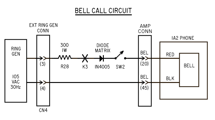 During ringing of ANY line, CPU1 also energizes the TIP32 power transistor Q4
whenever ANY line is ringing, providing +12 volts on the left two screws of
the "EXT RING GEN" terminal block (CN4) and pins #3 and #4 on JP5 which can be
used to directly power low voltage ring generator devices like the PowerDSINE
or BlackMagic ring generator modules.
This signal only provides power when any line is actively ringing, staying on
the entire ring cycle (e.g. between rings), and only turns off when no lines
are actively ringing.
This 12 volt output can also be used to drive an external relay to switch 115VAC
VAC power for AC powered ring generators via an externally provided ring relay,
so these types of ring generator can remain idle when no lines are ringing.
4.3.2.2 - Ring Programming
--------------------------
Ringing for each extension is programmable by the DIP switches SW2,
allowing the installer to configure which extensions will ring for
each of the two lines CO lines the board manages.
1A2 phones have a separate wire pair for the bell (amphenol pins #20
and #45), and a separate wire pair for the buzzer (amphenol pins #17
and #42). The bell runs on 105 VAC, the buzzer on approx 10 VAC.
The SW1 DIP switches control "BUZZER RINGING" where incoming calls can buzz
the buzzer at the usual ring cadence (1sec on, 3sec off).
The SW2 DIP switches control "BELL RINGING" where incoming calls can ring
the extension bells at the usual ring cadence.
During an incoming call, CPU1 will:
1) Flash the lamps at 1Hz for the line that's ringing, so the caller knows
which line to answer
2) Ring the appropriate extension phone's bells (or buzzers), based on the
configuration of SW1 and SW2.
The Bell System Practices (BSP's) recommends diodes be used for any kind of
"programmed" ringing, and the Seriss KSU imlements this using DIP switches
(instead of the old Western Electric diode matrix blocks).
Diodes chop off 1/2 of the AC cycle, but since the 1A2 bells are somewhat
polarity sensitive (they only actually ring on 1/2 the AC cycle), the diodes
don't really affect the sound of ringing. However it does mean the wiring
of the bells needs to be correct, or one might not hear ringing at all.
4.3.3 - Buzzer
--------------
The buzzer in 1A2 phones is used in two ways by the Seriss KSU:
o To get someone's attention to pickup the intercom
o An alternate audible to the bells for incoming calls
In this way the buzzer circuit is /shared/ by CPU1 and CPU2; CPU1 can run the
buzzers during incoming calls, and CPU2 can run the buzzers during intercom buzzing.
CPU1's ULN2803 (IC7) open collector outputs are mixed with CPU2's ULN2803 (IC12)
open collector outputs at the input pins on the 10K resistor net at RN2.
The 1A2 buzzers are normally rated for 10VAC to 18VAC at 60Hz. The Bell System
KSUs typically drove the buzzers with their 10VAC/60Hz power supply.
The Seriss KSU runs the buzzer with a 12 volt square wave generated by either
CPU1's PWM output (for incoming call ringing), or by CPU2's output for intercom
buzzing. These signals are combined and finally output directly to the buzzers
via TIP125 power transistors (Q7 - Q10).
4.3.3.1 - Buzzer Circuit
------------------------
The buzzer in each phone is connected to the Y-O pair (amphenol pins #42 and
#17) in order to operate with the Seriss KSU.
To buzz the buzzers, the KSU generates pseudo-AC in the form of a 12 volt
squarewave to drive the buzzers with TIP125 power transistors driving by
oscillating signals generated by CPU1 and/or CPU2, depending on what
source is triggering the buzzer.
Buzzer Idle
-----------
When the KSU is idle, the buzzers are all 'off'; both cpus buzzer outputs are
grounded, causing the associated ULN2803's to present open outputs to the base
of the TIP125 power transistors, which present an open output to the actual
buzzers. When the TIP125's base is left open, its input is internally pulled
up to +12v, preventing the transistor inputs from needing pullup resistors.
Buzz Ringing: Generated by CPU1
-------------------------------
If an extension is programmed to buzz during incoming call, it operates the
buzzer as it would the bell, with a 1sec 60Hz burst of a 12v squarewave,
and 3 seconds of silence.
When CPU1 detects an incoming call on either Line #1 or Line #2, it assigns
the PIC chip's PWM1 output to pin #15 (RC1), whose output then oscillates
from +5v to Gnd at 60Hz. This in turn drives a gate in the ULN2803 (IC7) to
turn on and off, alternating its output from being open to being closed to
ground. This alternating signal is passed to the NO pin on the two ring relays
K3 and K4, which depending on which line is ringing, switches this alternating
open-collector signal is passed to the diode matrix IC13 (an LED bar graph),
and on to the switch matrix at SW1. If the switches are "on", this signal is
then mixed with the outputs of the ULN2803 at IC12 (described below), passing
through a 10K current limiting resistor in RN2 before reaching the base of
the appropriate TIP125 (Q7 - Q10), turning the transistor on-and-off at 60Hz,
outputing a 12V squarewave.
1n4148 flyback diodes (D22 - D25) prevent inductor back current spikes from
the buzzers by shunting the spikes to ground. These spikes occur when the
TIP125 power transistors transition to "off". They're very short, but of
significant voltage, close to 200V.
During ringing of ANY line, CPU1 also energizes the TIP32 power transistor Q4
whenever ANY line is ringing, providing +12 volts on the left two screws of
the "EXT RING GEN" terminal block (CN4) and pins #3 and #4 on JP5 which can be
used to directly power low voltage ring generator devices like the PowerDSINE
or BlackMagic ring generator modules.
This signal only provides power when any line is actively ringing, staying on
the entire ring cycle (e.g. between rings), and only turns off when no lines
are actively ringing.
This 12 volt output can also be used to drive an external relay to switch 115VAC
VAC power for AC powered ring generators via an externally provided ring relay,
so these types of ring generator can remain idle when no lines are ringing.
4.3.2.2 - Ring Programming
--------------------------
Ringing for each extension is programmable by the DIP switches SW2,
allowing the installer to configure which extensions will ring for
each of the two lines CO lines the board manages.
1A2 phones have a separate wire pair for the bell (amphenol pins #20
and #45), and a separate wire pair for the buzzer (amphenol pins #17
and #42). The bell runs on 105 VAC, the buzzer on approx 10 VAC.
The SW1 DIP switches control "BUZZER RINGING" where incoming calls can buzz
the buzzer at the usual ring cadence (1sec on, 3sec off).
The SW2 DIP switches control "BELL RINGING" where incoming calls can ring
the extension bells at the usual ring cadence.
During an incoming call, CPU1 will:
1) Flash the lamps at 1Hz for the line that's ringing, so the caller knows
which line to answer
2) Ring the appropriate extension phone's bells (or buzzers), based on the
configuration of SW1 and SW2.
The Bell System Practices (BSP's) recommends diodes be used for any kind of
"programmed" ringing, and the Seriss KSU imlements this using DIP switches
(instead of the old Western Electric diode matrix blocks).
Diodes chop off 1/2 of the AC cycle, but since the 1A2 bells are somewhat
polarity sensitive (they only actually ring on 1/2 the AC cycle), the diodes
don't really affect the sound of ringing. However it does mean the wiring
of the bells needs to be correct, or one might not hear ringing at all.
4.3.3 - Buzzer
--------------
The buzzer in 1A2 phones is used in two ways by the Seriss KSU:
o To get someone's attention to pickup the intercom
o An alternate audible to the bells for incoming calls
In this way the buzzer circuit is /shared/ by CPU1 and CPU2; CPU1 can run the
buzzers during incoming calls, and CPU2 can run the buzzers during intercom buzzing.
CPU1's ULN2803 (IC7) open collector outputs are mixed with CPU2's ULN2803 (IC12)
open collector outputs at the input pins on the 10K resistor net at RN2.
The 1A2 buzzers are normally rated for 10VAC to 18VAC at 60Hz. The Bell System
KSUs typically drove the buzzers with their 10VAC/60Hz power supply.
The Seriss KSU runs the buzzer with a 12 volt square wave generated by either
CPU1's PWM output (for incoming call ringing), or by CPU2's output for intercom
buzzing. These signals are combined and finally output directly to the buzzers
via TIP125 power transistors (Q7 - Q10).
4.3.3.1 - Buzzer Circuit
------------------------
The buzzer in each phone is connected to the Y-O pair (amphenol pins #42 and
#17) in order to operate with the Seriss KSU.
To buzz the buzzers, the KSU generates pseudo-AC in the form of a 12 volt
squarewave to drive the buzzers with TIP125 power transistors driving by
oscillating signals generated by CPU1 and/or CPU2, depending on what
source is triggering the buzzer.
Buzzer Idle
-----------
When the KSU is idle, the buzzers are all 'off'; both cpus buzzer outputs are
grounded, causing the associated ULN2803's to present open outputs to the base
of the TIP125 power transistors, which present an open output to the actual
buzzers. When the TIP125's base is left open, its input is internally pulled
up to +12v, preventing the transistor inputs from needing pullup resistors.
Buzz Ringing: Generated by CPU1
-------------------------------
If an extension is programmed to buzz during incoming call, it operates the
buzzer as it would the bell, with a 1sec 60Hz burst of a 12v squarewave,
and 3 seconds of silence.
When CPU1 detects an incoming call on either Line #1 or Line #2, it assigns
the PIC chip's PWM1 output to pin #15 (RC1), whose output then oscillates
from +5v to Gnd at 60Hz. This in turn drives a gate in the ULN2803 (IC7) to
turn on and off, alternating its output from being open to being closed to
ground. This alternating signal is passed to the NO pin on the two ring relays
K3 and K4, which depending on which line is ringing, switches this alternating
open-collector signal is passed to the diode matrix IC13 (an LED bar graph),
and on to the switch matrix at SW1. If the switches are "on", this signal is
then mixed with the outputs of the ULN2803 at IC12 (described below), passing
through a 10K current limiting resistor in RN2 before reaching the base of
the appropriate TIP125 (Q7 - Q10), turning the transistor on-and-off at 60Hz,
outputing a 12V squarewave.
1n4148 flyback diodes (D22 - D25) prevent inductor back current spikes from
the buzzers by shunting the spikes to ground. These spikes occur when the
TIP125 power transistors transition to "off". They're very short, but of
significant voltage, close to 200V.
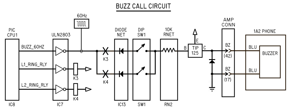 Intercom Buzzing: Generated by CPU2
-----------------------------------
When someone picks up the intercom line (Line #5) and dials an extension,
CPU2 operates the buzzer of that extension.
Both rotary and touch-tone are supported; touch tone dialing is detected by
the MT8870 (IC9), and generate a binary representation of the button pressed on
the A/B/C/D output pins and "StD" which are read by CPU2. Or, rotary dialing
briefly opens the Tip/Ring pair, causing CPU2 to read the pulse pattern on RC1,
decoding the digit dialed.
Either way, CPU2 reacts to the dialed number the same way: it outputs a 60Hz
signal on one of its 8 outputs, driving one of the appropriate gates in ULN2803
(IC12) through 10K current limiting resistors in RN2, which in turn drive the
appropriate TIP125 power transistors (Q7-Q10), similar to the above description
for "BUZZ RINGING".
Note that there are 8 outputs, but only 4 TIP125 transistors. This is because
when boards are interlinked, only the PRIMARY board's CPU2 manages the intercom
lines. For extensions 1 through 4, the TIP125's on the PRIMARY board drive the
buzzers. For extensions 5 through 8, the output signals from the 10K resistor
net are routed to the other board by way of JP3, pass over the ribbon cable,
and come back into the SECONDARY board at JP4, and are injected directly into
the base of the TIP125's to drive the buzzers in extensions 5 - 8.
### I YAM HERE ###
4.x 1A2 PHONE WIRING
--------------------
Sometimes the internal wiring of the 1A2 phones need to be modified to work properly
with the KSU. So before connecting up the phones, verify the phones are wired as
described in the "User Manual" installation section.
Usually the only wires that need modification, if any, are the buzzer and bell.
This board expects all phones to be internally wired the same way (if plugging
directly into the board), where:
o The phone's bell is wired to the 20/45 pair (yel/slt, slt/yel).
o The phone's buzzer is wired to the 17/42 pair (orn/yel, yel/orn).
For more info on the default internal wiring of 1A2 6 button phones, see:
http://seriss.com/people/erco/1a2/2564-pinout.html
The 1A2 6 button phones differ from regular phones in the following way:
A 50 pin cable instead of a single wire pair. This is because 1A2 phones are
capable of accessing any of 5 lines, and include additional control signals
regular phones don't have; lamps, switch closures, bell and buzzer options.
The 5 line buttons each have a 10VAC lamp, a separate wire pair for each. With
this 1A2 card, 12VDC is used to run the lamps, which at that voltage is around
~42 mA per lamp. So with a max of 4 phone sets, if Lines 1, 2 and 5 are all lit
at the same time, that's (3 x 4 x 42mA) or 504mA current draw for just the lamps.
When a button is down and the receiver is lifted, that button's switch closes
the "A lead" pair for that line. The KSU board uses this switch closure for
logic to handle its internal logic.
The "bell" (ringer), which singals people there's an incoming call, has its
own separate wire pair, and is NOT connected in any way to any of the Tip/Ring
pairs. It needs a separate 90VAC supply to ring the phone's bell. This is
because ringing can be programmed at the KSU to ring for more than one line,
and ringing can happen while someone's already on a call.
The "buzzer", used for intercom signalling, has a separate wire pair and runs
on 18VAC. With this board, 12VDC at 60Hz is used.
Other than that, the internals of the phone are mostly the same as
the old home phone sets; there's a voice hybrid, a switch hook,
a carbon-mic based handset, a touchtone dial, and tip/ring enters
the phone.
4.2 TELCO LINE
--------------
In the following description, voltages are approximate and vary by location.
The lines from the telephone company idle at 48 VDC.
Incoming calls presents 90VAC/20Hz on the line.
When someone picks up the call, the phone's hybrid presents a current draw
sensed by the phone company, which switches to a 6 VDC talk voltage that powers
the talk circuit of the phone.
4.3 CIRCUIT DESCRIPTION
-----------------------
Electronics are used to achieve the various needs of a 1A2 phone system:
o Controls lamps, bells, buzzers on the phones to give visual
and audio feedback.
o Manages line state detection and Hold functions
o Provides a local intercom system, including Touch-Tone buzzing
of extensions.
Simple circuitry is used to achive this; optocouplers (LDA-110), DPST 12 volt
relays (DS2Y-S-12VDC), linear comparitors (LM339), power transistors to control
lamps and buzzers (TIP125), and some DTMF circuitry (MT8870, 7445).
Linear comparitors are employed to serve a variety of functions.. they are used as
inverters, "relaxation oscillators", logic gates, signal converters, isolation gates.
By design, no computers or software is used in this circuit.
To understand the schematics, one needs to understand the phone company's unusual
relay symbols; this is a single pair of Normally Open (NO) and Normally Closed
(NC) RELAY TERMINALS with a Common (C) connection:
Intercom Buzzing: Generated by CPU2
-----------------------------------
When someone picks up the intercom line (Line #5) and dials an extension,
CPU2 operates the buzzer of that extension.
Both rotary and touch-tone are supported; touch tone dialing is detected by
the MT8870 (IC9), and generate a binary representation of the button pressed on
the A/B/C/D output pins and "StD" which are read by CPU2. Or, rotary dialing
briefly opens the Tip/Ring pair, causing CPU2 to read the pulse pattern on RC1,
decoding the digit dialed.
Either way, CPU2 reacts to the dialed number the same way: it outputs a 60Hz
signal on one of its 8 outputs, driving one of the appropriate gates in ULN2803
(IC12) through 10K current limiting resistors in RN2, which in turn drive the
appropriate TIP125 power transistors (Q7-Q10), similar to the above description
for "BUZZ RINGING".
Note that there are 8 outputs, but only 4 TIP125 transistors. This is because
when boards are interlinked, only the PRIMARY board's CPU2 manages the intercom
lines. For extensions 1 through 4, the TIP125's on the PRIMARY board drive the
buzzers. For extensions 5 through 8, the output signals from the 10K resistor
net are routed to the other board by way of JP3, pass over the ribbon cable,
and come back into the SECONDARY board at JP4, and are injected directly into
the base of the TIP125's to drive the buzzers in extensions 5 - 8.
### I YAM HERE ###
4.x 1A2 PHONE WIRING
--------------------
Sometimes the internal wiring of the 1A2 phones need to be modified to work properly
with the KSU. So before connecting up the phones, verify the phones are wired as
described in the "User Manual" installation section.
Usually the only wires that need modification, if any, are the buzzer and bell.
This board expects all phones to be internally wired the same way (if plugging
directly into the board), where:
o The phone's bell is wired to the 20/45 pair (yel/slt, slt/yel).
o The phone's buzzer is wired to the 17/42 pair (orn/yel, yel/orn).
For more info on the default internal wiring of 1A2 6 button phones, see:
http://seriss.com/people/erco/1a2/2564-pinout.html
The 1A2 6 button phones differ from regular phones in the following way:
A 50 pin cable instead of a single wire pair. This is because 1A2 phones are
capable of accessing any of 5 lines, and include additional control signals
regular phones don't have; lamps, switch closures, bell and buzzer options.
The 5 line buttons each have a 10VAC lamp, a separate wire pair for each. With
this 1A2 card, 12VDC is used to run the lamps, which at that voltage is around
~42 mA per lamp. So with a max of 4 phone sets, if Lines 1, 2 and 5 are all lit
at the same time, that's (3 x 4 x 42mA) or 504mA current draw for just the lamps.
When a button is down and the receiver is lifted, that button's switch closes
the "A lead" pair for that line. The KSU board uses this switch closure for
logic to handle its internal logic.
The "bell" (ringer), which singals people there's an incoming call, has its
own separate wire pair, and is NOT connected in any way to any of the Tip/Ring
pairs. It needs a separate 90VAC supply to ring the phone's bell. This is
because ringing can be programmed at the KSU to ring for more than one line,
and ringing can happen while someone's already on a call.
The "buzzer", used for intercom signalling, has a separate wire pair and runs
on 18VAC. With this board, 12VDC at 60Hz is used.
Other than that, the internals of the phone are mostly the same as
the old home phone sets; there's a voice hybrid, a switch hook,
a carbon-mic based handset, a touchtone dial, and tip/ring enters
the phone.
4.2 TELCO LINE
--------------
In the following description, voltages are approximate and vary by location.
The lines from the telephone company idle at 48 VDC.
Incoming calls presents 90VAC/20Hz on the line.
When someone picks up the call, the phone's hybrid presents a current draw
sensed by the phone company, which switches to a 6 VDC talk voltage that powers
the talk circuit of the phone.
4.3 CIRCUIT DESCRIPTION
-----------------------
Electronics are used to achieve the various needs of a 1A2 phone system:
o Controls lamps, bells, buzzers on the phones to give visual
and audio feedback.
o Manages line state detection and Hold functions
o Provides a local intercom system, including Touch-Tone buzzing
of extensions.
Simple circuitry is used to achive this; optocouplers (LDA-110), DPST 12 volt
relays (DS2Y-S-12VDC), linear comparitors (LM339), power transistors to control
lamps and buzzers (TIP125), and some DTMF circuitry (MT8870, 7445).
Linear comparitors are employed to serve a variety of functions.. they are used as
inverters, "relaxation oscillators", logic gates, signal converters, isolation gates.
By design, no computers or software is used in this circuit.
To understand the schematics, one needs to understand the phone company's unusual
relay symbols; this is a single pair of Normally Open (NO) and Normally Closed
(NC) RELAY TERMINALS with a Common (C) connection:
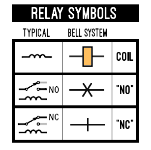 So when the relay is OFF, current flows through the NC contacts depicted this way:
 ..and when the relay is ON, current flows through the NO contacts depicted this way:
 4.3.1 - Phone Lines: Tip and Ring
---------------------------------
The circuit senses the telephone line for signals from the central
office (CO) and the local phone extensions (EXT) or 'stations' (STA).
Optocouplers are used to sense the phone line "tip" and "ring" pair;
one senses if the line is in use ("Line Detect"), the other senses
ring voltage if there's an incoming call ("Ring Detect").
Since the board supports two incoming lines, there's a separate pair
of optocouplers to sense these states for each line.
4.3.1.1 LINE SENSE CIRCUIT
--------------------------
The board needs to be able to detect when a line is in use for two purposes:
o To light the line's lamp indicating the line is in use
o Break a call out of "Hold" if the remote hangs up
For this, a single optocoupler is connected in series with the line to detect
current flow through the phone hybrids or the hold resistor (if a call is
on hold).
An LDA-110 optocoupler can pass AC or DC through them, due to the use of
back-to-back LEDs on the input. In this way it can detect current flow without
affecting the call.
When phones are not in use (hung up) and no calls are on hold, there is no
current flow across Tip/Ring, so the optocoupler's LEDs (on the LDA110's)
are both off.
When one or more phones are off-hook for a line, or a line is on Hold, the
"Line Detect" optocoupler operates, presenting its output to PIC CPU1 for
detection by the firmware logic, which then turns on the lamp driver
circuit to light the lamp for that line on all extensions.
4.3.1 - Phone Lines: Tip and Ring
---------------------------------
The circuit senses the telephone line for signals from the central
office (CO) and the local phone extensions (EXT) or 'stations' (STA).
Optocouplers are used to sense the phone line "tip" and "ring" pair;
one senses if the line is in use ("Line Detect"), the other senses
ring voltage if there's an incoming call ("Ring Detect").
Since the board supports two incoming lines, there's a separate pair
of optocouplers to sense these states for each line.
4.3.1.1 LINE SENSE CIRCUIT
--------------------------
The board needs to be able to detect when a line is in use for two purposes:
o To light the line's lamp indicating the line is in use
o Break a call out of "Hold" if the remote hangs up
For this, a single optocoupler is connected in series with the line to detect
current flow through the phone hybrids or the hold resistor (if a call is
on hold).
An LDA-110 optocoupler can pass AC or DC through them, due to the use of
back-to-back LEDs on the input. In this way it can detect current flow without
affecting the call.
When phones are not in use (hung up) and no calls are on hold, there is no
current flow across Tip/Ring, so the optocoupler's LEDs (on the LDA110's)
are both off.
When one or more phones are off-hook for a line, or a line is on Hold, the
"Line Detect" optocoupler operates, presenting its output to PIC CPU1 for
detection by the firmware logic, which then turns on the lamp driver
circuit to light the lamp for that line on all extensions.
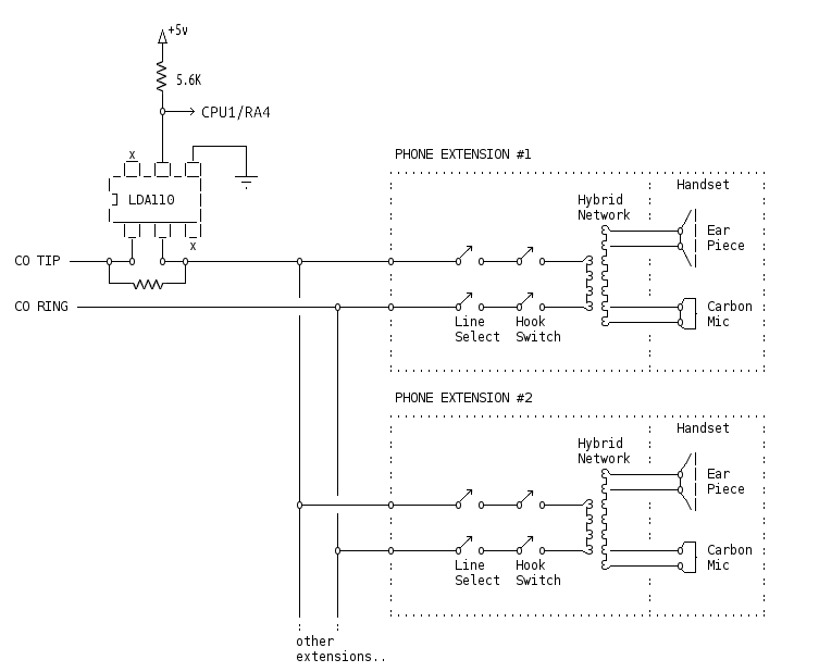 If someone puts the line on Hold by pressing down the Hold button,
this opens the A lead while the button is down, causing the firmware
to see the A lead released, but the Line Detect optocoupler stays on
(seeing current through that line's hybrid). The firmware then triggers
the Hold relay for that line to energize, connecting the Hold resistor
across Tip+Ring. Then, a fraction of a second later when the user releases
the Hold button, the button pops up, disconnecting the hybrid from the
line, and the firmware begins winking the line's lamp at the Hold flash
frequency. Now that the Hold relay is across the line, the Line Detect
optocoupler continues to see line current through the Hold resistor,
an indication the line remains on Hold.
Anyone answering the intercom line will cause the A lead to be connected,
causing the firmware to take the line out of Hold, causing the line lamp
to stop winking and return to a steady-on state, and the call continues.
If, while on Hold, the remote caller hangs up, the telco briefly opens
the line for about 1/4 second, causing current flow to stop, causing
the Line Detect optocoupler to turn off. The firmware sees this as a
call drop, so it deenergizes the Hold relay, causing the line to return
to an Idle state, so that it can be used to receive or make new calls.
4.3.2 Hold Circuit
------------------
The Hold circuit is simply a relay that shunts a Hold resistor across the Tip/Ring
pair to put a line on Hold.
Detecting Hold is done by comparing the state of the Line Detect and A Lead
optocouplers in the firmware.
When a phone call is in progress, e.g. on Line #1:
o "A lead "optocoupler (IC5) is "on"
o "Line Detect" optocoupler (IC2) is "on"
In this state the firmware knows the line is "in use", and keeps the line lamp on.
When someone presses Hold:
o "A lead" optocoupler (IC5) turns "off"
o "Line Detect" optocoupler (IC2) remains "on"
When someone presses down the Hold button on a 1A2 phone, it interrupts the
A lead for the line that was in use for as long as the button is down.
This causes the A lead optocoupler to immediately turn off. However, the voice
hybrid is still connected across the line, drawing current, keeping the Line Detect
optocoupler energized.
When the A lead drops, the firmware starts a timer to see if the Line Detect optocoupler
remains on for at least 1/10th of a second:
o If the Line Detect remains energized for 1/10sec, Hold was pressed
o If the Line Detect drops within 1/10sec, the line was hung up
This subtle difference is how to detect Hold vs. Hang Up.
When Hold is detected after 1/10th sec, the firmware energizes the Hold relay (K1)
which shunts the Hold resistor (R1) across the line, causing current to flow through it.
It also starts Line #1's lamp winking at the 2 Hz / 80% duty cycle rate,
a visual indication the line is now "on Hold".
Then, a fraction of a second later when the Hold button is /released/, the line button
on the phone pops up, disconnecting the voice hybrid from the Tip/Ring circuit, causing it
to no longer draw current. But now with the Hold relay shorting the Hold resistor across
the Tip/Ring pair, the Line Sense optocoupler continues to sense current flow, keeping the
optocoupler "on". Thus the line now remains locked in the Hold state:
> A lead optocoupler is "off"
> Line Detect optocoupler is "on" (current flow thru Hold resistor)
> Hold relay remains energized
> Line lamp winks at the Hold flashing rate
Two conditions can cause the line to fall out of Hold:
o Someone picks up the line
o Remote caller hangs up
If someone picks up the line, A lead optocoupler re-energizes, causing the
firmware to release the Hold relay, disconnecting the Hold resistor from the
line, and returns the Line lamp to being steady on, indicating the call is now
"in use".
If the remote caller hangs up while on Hold, the line remains on Hold until
the telco (central office) detects the remote call drop, and briefly opens
the line for 1/4 second (CPC or Disconnect Supervision) which causes line
current to disappear, deenergizing the Line Detect optocoupler. The firmware
sees this as a dropped call, and returns the line to an Idle state, turning
off the Hold relay and line lamp.
---
---
4.3.4 Incoming Calls
--------------------
When a line is ringing, the output of the "Ring Detect" optocoupler triggers the
firmware to detect ringing. This causes the firmware to react as follows:
o Start a 6 second "ring cycle" timer that keeps line lamps flashing and ringing
o Turns on TIP32 (Q4) providing +12V to pins 1 and 2 on the EXT RING GEN terminal block
o Turns on the appropriate ring relay (K3 or K4) depending on which line is ringing
o Enables a hardware 60hz PWM in the PIC to output its signal to the two ring relays
Each ring from the central office restarts the 6 second ring cycle timer, keeping it
running steadily for the entire time ringing is occurring. This keeps the line lamps
flashing, and keeps the ring generator power energized throughout the ring cycle.
So if an incoming call on Line #1 rings 3 times, and then hangs up, the KSU sees
this signalling from the CO, and generates the resulting signals as follows:
RING#1 RING#2 RING#3
||| ||| ||| CO's 90VAC/25Hz
CO: ________________|||_____________|||_____________|||__________________________________ ring bursts
: :
:<- - - - - - - - - - >:
: 6 secs :
Ring ________________________________________________________
Cycle | | (internal timer)
Timer ________________| |___________
_ _ _ _ _ _ _ _ _ _ _ _ _ _ _
Line | | | | | | | | | | | | | | | | | | | | | | | | | | | | | | (+12v)
Lamp ________________| |_| |_| |_| |_| |_| |_| |_| |_| |_| |_| |_| |_| |_| |_| |__________
_ _ _ _
K1 | | | | | | | | (Energized)
Relay ________________| |_____________| |_____________| |_____________| |__________________
________________________________________________________
TIP32 | | (+12V)
(Q4) ________________| |___________
60HZ |||||||||||||||||||||||||||||||||||||||||||||||||||||||||| (open collector)
BUZZ ________________||||||||||||||||||||||||||||||||||||||||||||||||||||||||||___________
L1 ||| ||| ||| ||| (+12v/60Hz)
BZ ________________|||_____________|||______________|||_____________|||_________________
L1 ||| ||| ||| ||| (105VAC/30Hz)
BELL ________________|||_____________|||______________|||_____________|||_________________
Of interest in the above:
Due to the 6 second ring timer, the lamps continue flashing and the bells/buzzers
continue an extra ring cycle past the last ring from the CO because it's not known
the caller hung up until the 6 second timer times out. This is consistent with the
old AT&T KSU's, and can't really be avoided when ringing is regenerated.
Both the "60Hz Buzz" output from the PIC CPU1 and the ring generator's output
remain on during the entire ring cycle, and are broken up into "bursts" by the
ring relays (K3 + K4), resulting in the output signals to buzzers ("L1 BZ")
and bells ("L1 BELL").
x.x Bell Call Programming
-------------------------
During ringing for an incoming call, CPU1 powers the TIP32 (Q4) providing
12v power that can be used by any ring generator that needs it to enable ring
generator voltage for ringing on either JP5 or pins 1 and 2 of the terminal
block at CN4.
AC ring voltage comes in either on JP5 or pins 3 and 4 of terminal block CN4, and
passes through a 300 ohm current limit resisor R28, and reaches the terminals on
ring relays K3 and K4. These relays are controlled by CPU1 by way of darlington
transistor gates on the ULN2803 (IC7), turned on for each ring burst to ring the
bells on the phones.
During a ring burst, AC ring voltage passes through the ring relay to the BELL CALL
diode network and DIP switches at SW2. The DIP switch allows any of the 4 extensions
to be programmed for bell ringing; 4 switches for Line #1, 4 switches for Line #2.
The diode network prevent back currents, enabling the programming, but looses
1/2 of the AC wave used for ringing. This is normal on 1A2 systems, which are
designed for either 1/2 cycle or full cycle ringing.
[DIAGRAM MOVED ABOVE]
x.x Buzz Call Programming
-------------------------
During ringing for an incoming call, CPU1 enables the PIC's internal PWM
hardware to generate a 60Hz output to ULN2803 (IC7) who's darlington output
is sent to the normally open terminals on the ring relays K3 + K4.
These relays are controlled by CPU1 by way of darlington transistor gates on
the ULN2803 (IC7), and are turned on for each ring burst (1 sec on, 3 sec off),
gating the 60Hz buzz signal.
This then passes through the ring relay to the BUZZ CALL diode network (IC13)
and DIP switches at SW1. The DIP switches allow any of the 4 extensions to be
programmed to buzz during an incoming call; 4 switches for Line #1, 4 switches
for Line #2.
The 60hz signal gated by the ring relays, and 'programmed' via the diode
network/DIP switches then pass through a 10K resistor network (RN2) that drives
the base of the TIP125 power transistors whose output provides the +12v / 60Hz
signal that directly drives the buzzer in each extension.
Flyback diodes (D22-D25) on the TIP125 outputs prevent inductive backcurrents
from the buzzers during off transistions.
[DIAGRAM MOVED ABOVE]
vvv I YAM HERE vvv
***** WORK IN PROGRESS: BELOW THIS LINE vvv
X.X INTERLINKED RINGING
-----------------------
In V1.3D firmware and / REV-J3 and older, ringing across boards was not synchronized,
and ringing across boards was supported only by the addition of the "L1+L2 BELL"
terminal block in REV-J3. Only lamp flashing is synchronized by signaling between
boards over the SYNC_ILINK pin common between both boards.
In V1.4 firmware / REV-J4 and newer, ringing across boards is synchronized by
implementing an "Interrupter" (implemented in Interrupter.h), which handles the
ring signal (on 1 sec, off 3 sec) and ring/hold flash signals. The signal's state
on the PRIMARY is sent as an 8bit value every 10 main loop iters to the SECONDARY,
which copies those signal states to its Interrupter, which drives its line lamps
and ringing.
The SECONDARY then replies with an 8bit data reply of its own, sending binary state
information about if any lines are ringing or on hold, so the PRIMARY board knows
to start its interrupter.
The V1.4 firmware uses the SECONDARY_DET input on CPU1 to determine if the firmware
should be running in PRIMARY or SECONDARY mode, since the PRIMARY needs to know
it starts all transmissions over SYNC_ILINK, and SECONDARY must take that data to
drive the Interrupter, and must only react with state info of its own.
X.X - V1.4 Firmware Trace Cut Needed For REV-J3 and Older
---------------------------------------------------------
NOTE: For V1.4 to work on REV-J3 and older boards, you MUST cut the trace from
CPU2's RA5 (pin 2), e.g.
:
| CPU 2
| +5V RA5 RA4 RA3
|_______________________________ _ _
| 1 | | 2 | # | 3 | | 4 |
|___| |___| # |___| |___|
# #
# #
diagonal # # <- DONT CUT this nearby trace!
trace cut --> \\ # #
here \\ #
#\\ # REV-J3 BOARD
# \\ # (or older)
via --> (O) #
#
This prevents SECONDARY_DET from being dragged to ground when CPU2 is
powered down (ICM on hook). Not an issue for REV-J4 and up, which has
this trace /removed/.
Implementation of Bidirectional Data Transmission
-------------------------------------------------
Some features of the PIC were used to implement doing clean
bidirectional data transmission of 8bit values over a single port:
> WPU (Weak PullUps) are used on SYNC_ILINK to hold the line
high so that the transmitter can pull it LOW when sending data.
> IOC (Interrupt On Change) is used on SYNC_ILINK to interrupt
the CPU when reading data from the board acting as a transmitter.
Interrupts occur on both RISING and FALLING edges of SYNC_ILINK
so that timing of how long signal remains low is possible.
> TMR0 (hardware timer) is used to time how long SYNC_ILINK is
pulled low:
> When SYNC_ILINK goes low, receiver interrupt zeroes TMR0
> When SYNC_ILINK goes high, receiver interrupt saves TMR0 value
which is later used to determine if 1 or 0 was sent
> Both boards leave SYNC_ILINK configured as an input
until the PRIMARY decides to send data.
> PRIMARY switches SYNC_ILINK to output mode, transmits 8bits,
then switches back to input mode
> SECONDARY reads the 8bits from PRIMARY, switches to output mode,
and sends its 8bit value, the switches back to input mode
The transmission of data is implemented such that a '1' bit holds
SYNC_ILINK low for a longer time than '0' the bits.
Features used by the PIC.
the first two bits being 'start' bits that are '1' and '0'
which the receiver records the timing of for reference to
later determine timing of the data bits that follow.
the binary data one bit at a time
using a longer delay for '1's vs '0's.
> The receiver board
***** WORK IN PROGRESS: ABOVE THIS LINE ^^^
4.5 Optional Extensions
-----------------------
The board supplies at least 4 extensions, and each can be dialed
for buzzing directly using the TouchTone dial pad by dialing 1 through 4.
But with 66 blocks, you can add an extra 4 extensions (for a total of 8)
that can be buzzed by the TouchTone dial pad by dialing 5 through 8.
See section 3.2 "EXPANDED WIRING: ADDING EXTRA EXTENSIONS #5-#8"
above for more info.
4.6 Debugging
-------------
4.6.1 - Status LEDS
-------------------
There are various status LEDs and test points on the board.
Each of the "LINE" sections has 3 status LEDs:
"L" -- lights when the "L" relay is operating (Line Detect).
"A" -- lights when the "A" relay is operating (A Lead)
"Line Use" -- this LED reflects the phone's lamp for that line;
on when in use, flashing during ring, winks during
a call on hold.
All LEDs are off when the system is idle.
Picking up a line should light all three LEDs: "L", "A", and "Line Use".
When an incoming call is ringing, "L" and "A" should be off,
and "Line Use" should flash.
When a call is on hold, the "L" light should be on, "A" should be off,
and the "Line Use" light should wink.
Debugging With a Meter
----------------------
Using a meter, you can test for +12/Gnd at the power connector
terminal screws. Ditto for the 90VAC/20Hz supply.
Each line has a row of test points along the top of the board,
to make it easy for a meter to access each of the 1A2 signals.
For instance:
Test Point Description
---------- --------------------------------------
STA T The station "Tip" signal from the telco.
STA R The station "Ring" signal from the telco.
STA AG The A lead's common ground. This is tied to the board's 12 volt ground.
STA A The A lead for the line. This will be grounded when a phone has the line picked up.
STA L The station lamp's +12 volt supply. This is tied to +12.
STA LG The lamp output. Grounded when the lamp is on.
To test the telco line for being idle, check for 48VDC across
"STA T" and "STA R". (Note that 90 VAC may be present on these
test points if the line is ringing)
To test the A lead for a line, look for 12 volts between
+12 and the "STA A" test point for that line (near the top of the board).
To test the lamp output, look for 12 volts between +12 and STA LG.
To test if the "ring detect" circuit is working, put a scope
between +12 and pin#5 of the "RING DET" optocoupler (LDA110).
When ringing is present, this should turn on and off.
To test if the "line sense" circuit is working, put a scope
between +12 and pin#5 of the "LINE SENSE" optocoupler (LDA110).
When the line is offhook or on hold, this should show 12 volts.
To test the hold lamp oscillator, you should see a steady 2Hz
"winking" 12 volt output at all times on pins #1 and #2 of LM339-A.
To test the ring lamp oscillator, you should see a steady 1Hz
12 volt square wave output at all times on pins #1 and #14 of LM339-D.
To test the 60Hz buzz oscillator, you should see a 60Hz
12 volt square wave output on pin #14 of LM339-E when
one of the dial buttons is pressed.
To test the DTMF detector, you should see +5 volts
on pin #15 of the MT8870 chip when someone is dialing
any digit on the intercom line. Depending on which dial
button is pressed, you should see 12 volts changing at 60Hz
between +12 and the appropriate open collector output pin on
the 7445. (e.g. dialing "1" should ground pin #2, dialing "2"
should ground pin #3..)
To test the buzzer outputs, you should see +12 alternating at
60Hz off the middle pin of the appropriate TIP125.
To test the intercom voice battery, you should see
between 6v and 12v across the "ICM T" and "ICM R"
in the "ICM VOICE BATT" section, and should see the
same across "STA T" and "STA R" on the "LINE 5 INTERCOM"
row of test points. "T" should be positive, and "R" should
be negative.
4.7 Examples
------------
4.7.1 - System Idle
-------------------
When the system is idle (waiting for a call or no one using a line),
relays "A" and "L" are off, lamps are all out, ringers and buzzers are
off. The state of the sensors:
The "Ring Detect" optocoupler is "off" because there's
insufficient AC current to light its LEDs through the
R/C pair.
The "Line Detect" optocoupler is "off" because there's
no current flow across tip/ring (no hybrids are drawing
current, and the hold resistor is switched out of the
circuit due to the relay logic).
The A leads on all phones are open.
The intercom talk battery and touchtone decoder are all
off because the intercom's A lead is open.
When both "A" and "L" relays are "off", their relay contacts
are arranged such that the output of the RING FLASH OSCILLATOR,
normally at ground unless there's ringing, is directed to the
LAMP OUTPUT TRANSISTOR, grounding it, causing the line's lamps
to be off.
Since RING FLASH OSCILLATOR is at ground when there's no rniging,
the line's ring output (STA RG) is idle.
4.6.2 - Incoming Call
---------------------
When a line rings, the central office (CO) sends 1 second
bursts of 90VAC, with ~4 seconds between each burst on the
Tip (CO T) and Ring (CO T) pair.
This drives the "Ring Detect" circuit, lighting the dual-LEDs
of an LDA-110 optocoupler, energizing its internal darlington
transitor for the duration of each ring burst.
The output of "Ring Detect" circuit is split into two:
1) Drives a "Ring Extension" circuit: a 2N3906 transistor
who's output remains high during ringing, who's output
is directed through a series of programmable DIP switches
(to control which extensions should ring for this line),
enabling the system's own 90 VAC ring voltage to ring
the phone sets programmed for ringing.
The pattern of ringing on the lines directly matches
the Central Office's pattern of ringing, but using
our own ring generator's voltage output.
2) Drives a "Ring Stretch" timing circuit that holds the
output low not only during ringing, but also between
ring bursts.
The output of this circuit is logically AND'ed with a
continuously running 60 IPM square wave generated by
the "Ring Lamp Osc" circuit.
The output of these combined signals creates the
on/off blinking pattern necessary to blink the lamps
for the ringing line.
This signal is presented to "normally open" contacts
of both "L" and "A" relays, which are both still "off"
during ringing, such that the signal causes the TIP-120
"LAMP OUTPUT TRANSISTOR" to turn on and off in the same
pattern, blinking the lamps on all extensions for this line.
If no one answers the call, after the last ring burst stops, the
"Ring Extension" circuit stops, and the "Ring Stretch" circuit
will switch back to a ground state, extinguishing the lamps.
During all of this, the "L" and "A" relays both remain off.
4.6.3 - Ringing Call Answered
-----------------------------
If someone answers the ringing call, several things happen
simultaneously:
o A user picking up the line causes the combination of
the phone's hook switch and depressed line button to:
1) Present the phone's "talk" hybrid across the line,
causing the Central Office to stop sending ringing,
and provide instead a 6VDC talk battery to the line.
2) Grounds the "A" lead (STA A) for this line
o The "Line Detect" optocoupler is triggered on because
it detects the 6VDC talk battery's current flow through
the answered phone's hybrid, operating the "L" relay.
o The grounded "A" lead operates the "A" relay.
o The "Ring Detect" optocoupler turns off immediately
due to the absence of ringing, causing the "Extension Ring"
circuit to turn off, extinguishing audible ringing.
o The absence of ringing will cause the timing capacitor
of the "Ring Stretch" circuit to stop re-triggering,
causing that circuit to run for no more than 6 seconds
after the CO provided ringing stops.
o The combined logic of the "A" and "L" relays redirect
the input of the "Lamp Output Transistor" away from the
"Ring Lamp Oscillator" output, and shunts it to +12 volts,
keeping the lamps in the continuous "on" state while the
call remains active.
Any leftover output from the "Ring Lamp Oscillator"
(up to 6 seconds due to the "Ring Stretch" timing circuit)
will be ignored.
NOTE: If the user answers the call and immediately hangs up within
6 seconds, the line's lamps may return to flashing as if ringing,
due to the 6 second "Ring Stretch" timing circuit still running
itself out from the last ring.
This small artifact could be avoided with a simple circuit
modification that resets the "Ring Stretch" circuit as soon as
the call is picked up, but currently this has not been done.
If I remember correctly, the old 1A2 KSU's (circa 1980) had this
same artifact, so for now I'm leaving it in.
4.6.4 - Placing Call On Hold
----------------------------
An active call is put on Hold when the user presses the Hold
button, which first opens the A lead, then removes the phone's
hybrid from Tip/Ring.
Pushing the Hold button causes the A relay to turn off,
dropping the Hold resistor across the Tip/Ring pair, immediately
and effectively "holding the line" by drawing enough current
flow to convince both the telco and the "Line Detect" circuit
that the call is still active.
The A relay going off also connects the "Hold Oscillator" output
to the lamps for this line, causing them to wink at 120 IPM.
When the user then releases the Hold button, the user's line button
mechanically pops up, removing the phone's hybrid from the line,
opening the station's Tip/Ring pair.
Normally this would hang up the call, but because the A relay's
logic dropped the Hold Resisior across the line, the line remains
active.
With the call now on "hold", one of two things can happen:
I. Someone Picks Up Call
------------------------
In the case of someone taking the call off hold, they press the line
button and pick up the handset, which:
o Connects the extension's hybrid across Tip/Ring
o Closes the A lead, operating the "A" relay, which:
1) Removing the Hold resistor from the line
2) Returns the lamps to a "continuous on" state
The call returns to a normal active state, the "Line Detect"
continues to detect current now going through the phone's
hybrid (instead of the Hold resistor), which keeps the "L"
relay operating.
II. Remote Caller Hangs Up
--------------------------
If the remote hangs up before someone retakes the call,
the Central Office briefly sends a CPC signal (Calling Party
Control), which briefly opens the Tip/Ring pair.
This causes the "Line Detect" optocoupler to turn off,
causing these events:
o The "L" relay to turn off, which:
1) Removes the Hold Resistor from the line
2) Stops the 120 IPM lamp from winking
3) Causes all lamps for the line to turn OFF.
o The A lead remains open (since the call was on hold),
so the "A" relay remains off.
This essentially resets the system from "Hold" to the
"Idle" state, ready to take new calls.
This behaivor is important to prevent the system from
remaining on hold even if no one is there, automatically
freeing up the line to accept new calls.
4.6.5 - Hanging Up an Active Call
---------------------------------
When an extension hangs up an active call, several things happen
simultaneously, returning the system to the Idle state:
o The phone's hybrid is removed from the line, causing the
telco to drop the talk voltage and return to the 48VDC line
idle state.
o The "Line Detect" optocoupler turns off because it
sees no current flow through the line, turning off
the "L" relay. This prevents the Hold Resistor from being
used, and returns the lamps to monitoring the "Ring
Detect" signal, which should be OFF when there's no ringing.
o The A lead for that line opens, turning the "A" relay off.
This leaves the system ready to receive new calls.
Parts List
----------
Parts are organized by section.
Quantities are the actual needed. Pad these out when ordering,
in case some parts are bad or for spares, especially of parts
that might become hard to find. (e.g. MT8870, LDA110s, DS2Y relays, etc)
All resistors are 1/4 watt unless otherwise specified.
Digikey part numbers are /suggestions/, and were used during R&D
and testing. Other parts of similar rating may be used.
Ordering Considerations
-----------------------
When ordering parts, most parts can be generally sourced with lax
tolerances, but some parts need special consideration.
Central Office Circuit Parts
----------------------------
Parts connected to the Central Office (CO) circuit are susceptible
to extreme electrical spikes and/or large voltage potentials due to
storms (lightning), or interaction with live AC or large voltage
potentials relative to ground.
As such, these parts SHOULD be:
o Flame retardant
o Resistors should be of high wattage (1/2W or more)
Parts falling into this category:
o Hold Resistors
o All parts on the CO side of the optocouplers
o All parts involved in the Tip/Ring circuit
Capacitors: Polarized vs. Unpolarized
-------------------------------------
Capacitors without "+" markings /MUST/ be UNpolarized.
Capacitors with "+" markings /can/ be polarized but don't have to be.
Diodes
------
There are 3 kinds of diodes used in this circuit.
1. Buzzer Programming Diodes - "BUZZ CALL" Section
--------------------------------------------------
These diodes can be small signal diodes, like the 1N914
(Digikey #1N914VSCT-ND).
2. Relay Coil Flyback Diodes
----------------------------
These diodes are arranged "backwards" across all relay coils to suppress inductive
back currents when the relay's coil switches off.
These should be rated 10 times the supply voltage, so in the case of 12 volt relays,
120 volts or higher should be used.
3. Ring Programming Diodes ("BELL CALL" Section)
------------------------------------------------
The ring programming diodes must handle 90VAC/30Hz and peak voltages
for the inductive load presented by the bell ringers.
Bell System Practices recommends the Western Electric "446F" diodes,
which have an NTE equivalent of NTE-5809, or a 1N5408. These
are rated 3A 1000V V(RRM). Digikey part# 1N5408DICT-ND is
approximately equivalent ($0.32 each).
Someone on the 1A2 board at Sundance Communications recommended
IN4005 (1A / 600V) which is under spec of Bell Labs, but is probably
more than sufficient, since the ringing voltages are local, not CO.
(Digikey #1N4005-TPMSCT-ND, $0.10 each).
NOTE 1: The silk screen diode diagram for the ring programming diodes
on the "REV B" boards are backwards. When soldering in the diodes
for these REV B boards, keep that in mind. The direction of the
diodes DOES MATTER, even though these are A/C signals. The ringers
tend to ring only on one side of the AC signal!
NOTE 2: To properly ring 1A2 phones through diodes, the hybrid networks
on each extension must have the K wire moved to the A screw. This
takes the hybrid's internal capacitor out of the circuit, which
defeats the diode oriented ringing signal. This practice was
something done by the old bell system installers when diode
were used to program ringing.
Sockets
-------
All IC chips SHOULD be socketed for proper servicing/debugging.
No Heat Sinks
-------------
The circuit is designed for components to run cool during use.
Power transistors and voltage regulators should NOT need heat sinks.
Any parts getting hot enough to need a heat sink indicates
SOMETHING IS WRONG. Most likely causes:
Wiring inside the phones
Wiring between phones and board
Metal objects are shorted across the back of the board
Part Specifications: Flexibility
--------------------------------
Many of the parts do not need precise values, and a range can be used:
o The HOLD RESISTOR is spec'ed at 160 ohms, but 120 may also be used.
o The RING DET resistor speced at 56K can be 50K-60K.
o The 5.6k resistor network RN1 can also be 4.7K, or any value
in between.
o The large female RJ21 connectors can be either "press fit"
or solder style. These connectors often have many monikers;
"50 pin" or "25PR" (25 pair) telco connectors, Amphenol connectors.
They are 100% compatible with "50 pin SCSI connectors". Just be
sure the lead diameter and spacing is consistent with what the
circuit board provides.
o LDA110 optocouplers may also be other "AC INPUT" darlington optos,
such as H11AA1.
It's critical the opto's inputs have back-to-back facing LED diodes
in cases where the opto is used as part of the voice circuit. For others,
such as the A1 and A2 optos, this is not necessary, and DC input optos
may be used, provided the input polarity is correct.
o Power connections can be simple screw terminals, though pluggable screw
terminals specified are advised for easy servicing/board swaps.
o Any capacitors marked with "+" can be either polarized OR unpolarized.
Caps without the "+" MUST be unpolarized.
( ) GENERAL BOARD LAYOUT
( ) POWER
( ) CO LINE CIRCUIT
( ) INTERCOM CIRCUIT
( ) BELL CALL
( ) RING GEN POWER
( ) BUZZ CALL
( ) EXTENSION CONNECTORS
( ) 1A2 PHONE
( ) VOICE CIRCUIT - TIP/RING PAIRS (per line)
( ) OUTPUTS FROM PHONE - A LEAD (per line)
( ) INPUTS TO PHONE - LAMP (per line), SINGLE BELL, SINGLE BUZZER
( ) MAKING OUTBOUND CALL
( ) Idle
( ) Pickup
( ) Dial
( ) Hangup
( ) INCOMING CALL
(x) Bell Call
(x) Buzz Call
(x) Ring Programming
( ) Answering
( ) CALL IN PROGRESS
( ) Talking
( ) Hold
( ) Hangup
( ) INTERCOM CALL - LINE 5
( ) Idle
( ) Pickup
( ) TouchTone Dial
( ) Rotary Dial
( ) Talk
( ) Hangup
3.0 - Design History
--------------------
When designing this board from scratch, a prototyping board was used to
develop the circuit, and aligator clip jumpers leads connected the protoboard
to a 66 block with a 1A2 phone plugged into it to test the phone's own circuits.
The first problem to tackle was the ring detect and line detect circuits.
I studied various patents, a variety of BSP documents, such as the Western Electric
400 type line card circuits and KSU schematics.
Once that was designed, the Hold circuit was developed. This could discriminate
between a Hold button being pressed, and a hangup. Hold triggered a relay to lock
the Hold resistor across the line, putting the call on Hold, and would release on
an extension pickup. I also checked that CPC/Disconnect Supervision from the CO
could properly reset a call on Hold.
Next the intercom circuit was developed, starting with the voice battery,
and then integrating the DTMF decoder for extension dialing. Later, a rotary
detect circuit was designed using a PIC to count the rotary pulses.
Once these circuits were working, a PCB board design was created, REV B,
which used linear components and digital logic, no CPUs.
Later tests were done with a PIC chip to simplify the design and implement
features hard to implement with pure linear logic. This allowed software
development to evolve without making changes to the board.
Over a series of board revisions, necessary features and tweaks were made
to the board layout to support different kinds of phones, and solve particular
user and board assembly issues.
REV-J4 is the culmination of all such features, and is the latest revision to
date as of this writing.
CHAR TEST:
~!@#$%^&*()_+
`1234567890-=
{}|[]\
:";'
<>?,./
If someone puts the line on Hold by pressing down the Hold button,
this opens the A lead while the button is down, causing the firmware
to see the A lead released, but the Line Detect optocoupler stays on
(seeing current through that line's hybrid). The firmware then triggers
the Hold relay for that line to energize, connecting the Hold resistor
across Tip+Ring. Then, a fraction of a second later when the user releases
the Hold button, the button pops up, disconnecting the hybrid from the
line, and the firmware begins winking the line's lamp at the Hold flash
frequency. Now that the Hold relay is across the line, the Line Detect
optocoupler continues to see line current through the Hold resistor,
an indication the line remains on Hold.
Anyone answering the intercom line will cause the A lead to be connected,
causing the firmware to take the line out of Hold, causing the line lamp
to stop winking and return to a steady-on state, and the call continues.
If, while on Hold, the remote caller hangs up, the telco briefly opens
the line for about 1/4 second, causing current flow to stop, causing
the Line Detect optocoupler to turn off. The firmware sees this as a
call drop, so it deenergizes the Hold relay, causing the line to return
to an Idle state, so that it can be used to receive or make new calls.
4.3.2 Hold Circuit
------------------
The Hold circuit is simply a relay that shunts a Hold resistor across the Tip/Ring
pair to put a line on Hold.
Detecting Hold is done by comparing the state of the Line Detect and A Lead
optocouplers in the firmware.
When a phone call is in progress, e.g. on Line #1:
o "A lead "optocoupler (IC5) is "on"
o "Line Detect" optocoupler (IC2) is "on"
In this state the firmware knows the line is "in use", and keeps the line lamp on.
When someone presses Hold:
o "A lead" optocoupler (IC5) turns "off"
o "Line Detect" optocoupler (IC2) remains "on"
When someone presses down the Hold button on a 1A2 phone, it interrupts the
A lead for the line that was in use for as long as the button is down.
This causes the A lead optocoupler to immediately turn off. However, the voice
hybrid is still connected across the line, drawing current, keeping the Line Detect
optocoupler energized.
When the A lead drops, the firmware starts a timer to see if the Line Detect optocoupler
remains on for at least 1/10th of a second:
o If the Line Detect remains energized for 1/10sec, Hold was pressed
o If the Line Detect drops within 1/10sec, the line was hung up
This subtle difference is how to detect Hold vs. Hang Up.
When Hold is detected after 1/10th sec, the firmware energizes the Hold relay (K1)
which shunts the Hold resistor (R1) across the line, causing current to flow through it.
It also starts Line #1's lamp winking at the 2 Hz / 80% duty cycle rate,
a visual indication the line is now "on Hold".
Then, a fraction of a second later when the Hold button is /released/, the line button
on the phone pops up, disconnecting the voice hybrid from the Tip/Ring circuit, causing it
to no longer draw current. But now with the Hold relay shorting the Hold resistor across
the Tip/Ring pair, the Line Sense optocoupler continues to sense current flow, keeping the
optocoupler "on". Thus the line now remains locked in the Hold state:
> A lead optocoupler is "off"
> Line Detect optocoupler is "on" (current flow thru Hold resistor)
> Hold relay remains energized
> Line lamp winks at the Hold flashing rate
Two conditions can cause the line to fall out of Hold:
o Someone picks up the line
o Remote caller hangs up
If someone picks up the line, A lead optocoupler re-energizes, causing the
firmware to release the Hold relay, disconnecting the Hold resistor from the
line, and returns the Line lamp to being steady on, indicating the call is now
"in use".
If the remote caller hangs up while on Hold, the line remains on Hold until
the telco (central office) detects the remote call drop, and briefly opens
the line for 1/4 second (CPC or Disconnect Supervision) which causes line
current to disappear, deenergizing the Line Detect optocoupler. The firmware
sees this as a dropped call, and returns the line to an Idle state, turning
off the Hold relay and line lamp.
---
---
4.3.4 Incoming Calls
--------------------
When a line is ringing, the output of the "Ring Detect" optocoupler triggers the
firmware to detect ringing. This causes the firmware to react as follows:
o Start a 6 second "ring cycle" timer that keeps line lamps flashing and ringing
o Turns on TIP32 (Q4) providing +12V to pins 1 and 2 on the EXT RING GEN terminal block
o Turns on the appropriate ring relay (K3 or K4) depending on which line is ringing
o Enables a hardware 60hz PWM in the PIC to output its signal to the two ring relays
Each ring from the central office restarts the 6 second ring cycle timer, keeping it
running steadily for the entire time ringing is occurring. This keeps the line lamps
flashing, and keeps the ring generator power energized throughout the ring cycle.
So if an incoming call on Line #1 rings 3 times, and then hangs up, the KSU sees
this signalling from the CO, and generates the resulting signals as follows:
RING#1 RING#2 RING#3
||| ||| ||| CO's 90VAC/25Hz
CO: ________________|||_____________|||_____________|||__________________________________ ring bursts
: :
:<- - - - - - - - - - >:
: 6 secs :
Ring ________________________________________________________
Cycle | | (internal timer)
Timer ________________| |___________
_ _ _ _ _ _ _ _ _ _ _ _ _ _ _
Line | | | | | | | | | | | | | | | | | | | | | | | | | | | | | | (+12v)
Lamp ________________| |_| |_| |_| |_| |_| |_| |_| |_| |_| |_| |_| |_| |_| |_| |__________
_ _ _ _
K1 | | | | | | | | (Energized)
Relay ________________| |_____________| |_____________| |_____________| |__________________
________________________________________________________
TIP32 | | (+12V)
(Q4) ________________| |___________
60HZ |||||||||||||||||||||||||||||||||||||||||||||||||||||||||| (open collector)
BUZZ ________________||||||||||||||||||||||||||||||||||||||||||||||||||||||||||___________
L1 ||| ||| ||| ||| (+12v/60Hz)
BZ ________________|||_____________|||______________|||_____________|||_________________
L1 ||| ||| ||| ||| (105VAC/30Hz)
BELL ________________|||_____________|||______________|||_____________|||_________________
Of interest in the above:
Due to the 6 second ring timer, the lamps continue flashing and the bells/buzzers
continue an extra ring cycle past the last ring from the CO because it's not known
the caller hung up until the 6 second timer times out. This is consistent with the
old AT&T KSU's, and can't really be avoided when ringing is regenerated.
Both the "60Hz Buzz" output from the PIC CPU1 and the ring generator's output
remain on during the entire ring cycle, and are broken up into "bursts" by the
ring relays (K3 + K4), resulting in the output signals to buzzers ("L1 BZ")
and bells ("L1 BELL").
x.x Bell Call Programming
-------------------------
During ringing for an incoming call, CPU1 powers the TIP32 (Q4) providing
12v power that can be used by any ring generator that needs it to enable ring
generator voltage for ringing on either JP5 or pins 1 and 2 of the terminal
block at CN4.
AC ring voltage comes in either on JP5 or pins 3 and 4 of terminal block CN4, and
passes through a 300 ohm current limit resisor R28, and reaches the terminals on
ring relays K3 and K4. These relays are controlled by CPU1 by way of darlington
transistor gates on the ULN2803 (IC7), turned on for each ring burst to ring the
bells on the phones.
During a ring burst, AC ring voltage passes through the ring relay to the BELL CALL
diode network and DIP switches at SW2. The DIP switch allows any of the 4 extensions
to be programmed for bell ringing; 4 switches for Line #1, 4 switches for Line #2.
The diode network prevent back currents, enabling the programming, but looses
1/2 of the AC wave used for ringing. This is normal on 1A2 systems, which are
designed for either 1/2 cycle or full cycle ringing.
[DIAGRAM MOVED ABOVE]
x.x Buzz Call Programming
-------------------------
During ringing for an incoming call, CPU1 enables the PIC's internal PWM
hardware to generate a 60Hz output to ULN2803 (IC7) who's darlington output
is sent to the normally open terminals on the ring relays K3 + K4.
These relays are controlled by CPU1 by way of darlington transistor gates on
the ULN2803 (IC7), and are turned on for each ring burst (1 sec on, 3 sec off),
gating the 60Hz buzz signal.
This then passes through the ring relay to the BUZZ CALL diode network (IC13)
and DIP switches at SW1. The DIP switches allow any of the 4 extensions to be
programmed to buzz during an incoming call; 4 switches for Line #1, 4 switches
for Line #2.
The 60hz signal gated by the ring relays, and 'programmed' via the diode
network/DIP switches then pass through a 10K resistor network (RN2) that drives
the base of the TIP125 power transistors whose output provides the +12v / 60Hz
signal that directly drives the buzzer in each extension.
Flyback diodes (D22-D25) on the TIP125 outputs prevent inductive backcurrents
from the buzzers during off transistions.
[DIAGRAM MOVED ABOVE]
vvv I YAM HERE vvv
***** WORK IN PROGRESS: BELOW THIS LINE vvv
X.X INTERLINKED RINGING
-----------------------
In V1.3D firmware and / REV-J3 and older, ringing across boards was not synchronized,
and ringing across boards was supported only by the addition of the "L1+L2 BELL"
terminal block in REV-J3. Only lamp flashing is synchronized by signaling between
boards over the SYNC_ILINK pin common between both boards.
In V1.4 firmware / REV-J4 and newer, ringing across boards is synchronized by
implementing an "Interrupter" (implemented in Interrupter.h), which handles the
ring signal (on 1 sec, off 3 sec) and ring/hold flash signals. The signal's state
on the PRIMARY is sent as an 8bit value every 10 main loop iters to the SECONDARY,
which copies those signal states to its Interrupter, which drives its line lamps
and ringing.
The SECONDARY then replies with an 8bit data reply of its own, sending binary state
information about if any lines are ringing or on hold, so the PRIMARY board knows
to start its interrupter.
The V1.4 firmware uses the SECONDARY_DET input on CPU1 to determine if the firmware
should be running in PRIMARY or SECONDARY mode, since the PRIMARY needs to know
it starts all transmissions over SYNC_ILINK, and SECONDARY must take that data to
drive the Interrupter, and must only react with state info of its own.
X.X - V1.4 Firmware Trace Cut Needed For REV-J3 and Older
---------------------------------------------------------
NOTE: For V1.4 to work on REV-J3 and older boards, you MUST cut the trace from
CPU2's RA5 (pin 2), e.g.
:
| CPU 2
| +5V RA5 RA4 RA3
|_______________________________ _ _
| 1 | | 2 | # | 3 | | 4 |
|___| |___| # |___| |___|
# #
# #
diagonal # # <- DONT CUT this nearby trace!
trace cut --> \\ # #
here \\ #
#\\ # REV-J3 BOARD
# \\ # (or older)
via --> (O) #
#
This prevents SECONDARY_DET from being dragged to ground when CPU2 is
powered down (ICM on hook). Not an issue for REV-J4 and up, which has
this trace /removed/.
Implementation of Bidirectional Data Transmission
-------------------------------------------------
Some features of the PIC were used to implement doing clean
bidirectional data transmission of 8bit values over a single port:
> WPU (Weak PullUps) are used on SYNC_ILINK to hold the line
high so that the transmitter can pull it LOW when sending data.
> IOC (Interrupt On Change) is used on SYNC_ILINK to interrupt
the CPU when reading data from the board acting as a transmitter.
Interrupts occur on both RISING and FALLING edges of SYNC_ILINK
so that timing of how long signal remains low is possible.
> TMR0 (hardware timer) is used to time how long SYNC_ILINK is
pulled low:
> When SYNC_ILINK goes low, receiver interrupt zeroes TMR0
> When SYNC_ILINK goes high, receiver interrupt saves TMR0 value
which is later used to determine if 1 or 0 was sent
> Both boards leave SYNC_ILINK configured as an input
until the PRIMARY decides to send data.
> PRIMARY switches SYNC_ILINK to output mode, transmits 8bits,
then switches back to input mode
> SECONDARY reads the 8bits from PRIMARY, switches to output mode,
and sends its 8bit value, the switches back to input mode
The transmission of data is implemented such that a '1' bit holds
SYNC_ILINK low for a longer time than '0' the bits.
Features used by the PIC.
the first two bits being 'start' bits that are '1' and '0'
which the receiver records the timing of for reference to
later determine timing of the data bits that follow.
the binary data one bit at a time
using a longer delay for '1's vs '0's.
> The receiver board
***** WORK IN PROGRESS: ABOVE THIS LINE ^^^
4.5 Optional Extensions
-----------------------
The board supplies at least 4 extensions, and each can be dialed
for buzzing directly using the TouchTone dial pad by dialing 1 through 4.
But with 66 blocks, you can add an extra 4 extensions (for a total of 8)
that can be buzzed by the TouchTone dial pad by dialing 5 through 8.
See section 3.2 "EXPANDED WIRING: ADDING EXTRA EXTENSIONS #5-#8"
above for more info.
4.6 Debugging
-------------
4.6.1 - Status LEDS
-------------------
There are various status LEDs and test points on the board.
Each of the "LINE" sections has 3 status LEDs:
"L" -- lights when the "L" relay is operating (Line Detect).
"A" -- lights when the "A" relay is operating (A Lead)
"Line Use" -- this LED reflects the phone's lamp for that line;
on when in use, flashing during ring, winks during
a call on hold.
All LEDs are off when the system is idle.
Picking up a line should light all three LEDs: "L", "A", and "Line Use".
When an incoming call is ringing, "L" and "A" should be off,
and "Line Use" should flash.
When a call is on hold, the "L" light should be on, "A" should be off,
and the "Line Use" light should wink.
Debugging With a Meter
----------------------
Using a meter, you can test for +12/Gnd at the power connector
terminal screws. Ditto for the 90VAC/20Hz supply.
Each line has a row of test points along the top of the board,
to make it easy for a meter to access each of the 1A2 signals.
For instance:
Test Point Description
---------- --------------------------------------
STA T The station "Tip" signal from the telco.
STA R The station "Ring" signal from the telco.
STA AG The A lead's common ground. This is tied to the board's 12 volt ground.
STA A The A lead for the line. This will be grounded when a phone has the line picked up.
STA L The station lamp's +12 volt supply. This is tied to +12.
STA LG The lamp output. Grounded when the lamp is on.
To test the telco line for being idle, check for 48VDC across
"STA T" and "STA R". (Note that 90 VAC may be present on these
test points if the line is ringing)
To test the A lead for a line, look for 12 volts between
+12 and the "STA A" test point for that line (near the top of the board).
To test the lamp output, look for 12 volts between +12 and STA LG.
To test if the "ring detect" circuit is working, put a scope
between +12 and pin#5 of the "RING DET" optocoupler (LDA110).
When ringing is present, this should turn on and off.
To test if the "line sense" circuit is working, put a scope
between +12 and pin#5 of the "LINE SENSE" optocoupler (LDA110).
When the line is offhook or on hold, this should show 12 volts.
To test the hold lamp oscillator, you should see a steady 2Hz
"winking" 12 volt output at all times on pins #1 and #2 of LM339-A.
To test the ring lamp oscillator, you should see a steady 1Hz
12 volt square wave output at all times on pins #1 and #14 of LM339-D.
To test the 60Hz buzz oscillator, you should see a 60Hz
12 volt square wave output on pin #14 of LM339-E when
one of the dial buttons is pressed.
To test the DTMF detector, you should see +5 volts
on pin #15 of the MT8870 chip when someone is dialing
any digit on the intercom line. Depending on which dial
button is pressed, you should see 12 volts changing at 60Hz
between +12 and the appropriate open collector output pin on
the 7445. (e.g. dialing "1" should ground pin #2, dialing "2"
should ground pin #3..)
To test the buzzer outputs, you should see +12 alternating at
60Hz off the middle pin of the appropriate TIP125.
To test the intercom voice battery, you should see
between 6v and 12v across the "ICM T" and "ICM R"
in the "ICM VOICE BATT" section, and should see the
same across "STA T" and "STA R" on the "LINE 5 INTERCOM"
row of test points. "T" should be positive, and "R" should
be negative.
4.7 Examples
------------
4.7.1 - System Idle
-------------------
When the system is idle (waiting for a call or no one using a line),
relays "A" and "L" are off, lamps are all out, ringers and buzzers are
off. The state of the sensors:
The "Ring Detect" optocoupler is "off" because there's
insufficient AC current to light its LEDs through the
R/C pair.
The "Line Detect" optocoupler is "off" because there's
no current flow across tip/ring (no hybrids are drawing
current, and the hold resistor is switched out of the
circuit due to the relay logic).
The A leads on all phones are open.
The intercom talk battery and touchtone decoder are all
off because the intercom's A lead is open.
When both "A" and "L" relays are "off", their relay contacts
are arranged such that the output of the RING FLASH OSCILLATOR,
normally at ground unless there's ringing, is directed to the
LAMP OUTPUT TRANSISTOR, grounding it, causing the line's lamps
to be off.
Since RING FLASH OSCILLATOR is at ground when there's no rniging,
the line's ring output (STA RG) is idle.
4.6.2 - Incoming Call
---------------------
When a line rings, the central office (CO) sends 1 second
bursts of 90VAC, with ~4 seconds between each burst on the
Tip (CO T) and Ring (CO T) pair.
This drives the "Ring Detect" circuit, lighting the dual-LEDs
of an LDA-110 optocoupler, energizing its internal darlington
transitor for the duration of each ring burst.
The output of "Ring Detect" circuit is split into two:
1) Drives a "Ring Extension" circuit: a 2N3906 transistor
who's output remains high during ringing, who's output
is directed through a series of programmable DIP switches
(to control which extensions should ring for this line),
enabling the system's own 90 VAC ring voltage to ring
the phone sets programmed for ringing.
The pattern of ringing on the lines directly matches
the Central Office's pattern of ringing, but using
our own ring generator's voltage output.
2) Drives a "Ring Stretch" timing circuit that holds the
output low not only during ringing, but also between
ring bursts.
The output of this circuit is logically AND'ed with a
continuously running 60 IPM square wave generated by
the "Ring Lamp Osc" circuit.
The output of these combined signals creates the
on/off blinking pattern necessary to blink the lamps
for the ringing line.
This signal is presented to "normally open" contacts
of both "L" and "A" relays, which are both still "off"
during ringing, such that the signal causes the TIP-120
"LAMP OUTPUT TRANSISTOR" to turn on and off in the same
pattern, blinking the lamps on all extensions for this line.
If no one answers the call, after the last ring burst stops, the
"Ring Extension" circuit stops, and the "Ring Stretch" circuit
will switch back to a ground state, extinguishing the lamps.
During all of this, the "L" and "A" relays both remain off.
4.6.3 - Ringing Call Answered
-----------------------------
If someone answers the ringing call, several things happen
simultaneously:
o A user picking up the line causes the combination of
the phone's hook switch and depressed line button to:
1) Present the phone's "talk" hybrid across the line,
causing the Central Office to stop sending ringing,
and provide instead a 6VDC talk battery to the line.
2) Grounds the "A" lead (STA A) for this line
o The "Line Detect" optocoupler is triggered on because
it detects the 6VDC talk battery's current flow through
the answered phone's hybrid, operating the "L" relay.
o The grounded "A" lead operates the "A" relay.
o The "Ring Detect" optocoupler turns off immediately
due to the absence of ringing, causing the "Extension Ring"
circuit to turn off, extinguishing audible ringing.
o The absence of ringing will cause the timing capacitor
of the "Ring Stretch" circuit to stop re-triggering,
causing that circuit to run for no more than 6 seconds
after the CO provided ringing stops.
o The combined logic of the "A" and "L" relays redirect
the input of the "Lamp Output Transistor" away from the
"Ring Lamp Oscillator" output, and shunts it to +12 volts,
keeping the lamps in the continuous "on" state while the
call remains active.
Any leftover output from the "Ring Lamp Oscillator"
(up to 6 seconds due to the "Ring Stretch" timing circuit)
will be ignored.
NOTE: If the user answers the call and immediately hangs up within
6 seconds, the line's lamps may return to flashing as if ringing,
due to the 6 second "Ring Stretch" timing circuit still running
itself out from the last ring.
This small artifact could be avoided with a simple circuit
modification that resets the "Ring Stretch" circuit as soon as
the call is picked up, but currently this has not been done.
If I remember correctly, the old 1A2 KSU's (circa 1980) had this
same artifact, so for now I'm leaving it in.
4.6.4 - Placing Call On Hold
----------------------------
An active call is put on Hold when the user presses the Hold
button, which first opens the A lead, then removes the phone's
hybrid from Tip/Ring.
Pushing the Hold button causes the A relay to turn off,
dropping the Hold resistor across the Tip/Ring pair, immediately
and effectively "holding the line" by drawing enough current
flow to convince both the telco and the "Line Detect" circuit
that the call is still active.
The A relay going off also connects the "Hold Oscillator" output
to the lamps for this line, causing them to wink at 120 IPM.
When the user then releases the Hold button, the user's line button
mechanically pops up, removing the phone's hybrid from the line,
opening the station's Tip/Ring pair.
Normally this would hang up the call, but because the A relay's
logic dropped the Hold Resisior across the line, the line remains
active.
With the call now on "hold", one of two things can happen:
I. Someone Picks Up Call
------------------------
In the case of someone taking the call off hold, they press the line
button and pick up the handset, which:
o Connects the extension's hybrid across Tip/Ring
o Closes the A lead, operating the "A" relay, which:
1) Removing the Hold resistor from the line
2) Returns the lamps to a "continuous on" state
The call returns to a normal active state, the "Line Detect"
continues to detect current now going through the phone's
hybrid (instead of the Hold resistor), which keeps the "L"
relay operating.
II. Remote Caller Hangs Up
--------------------------
If the remote hangs up before someone retakes the call,
the Central Office briefly sends a CPC signal (Calling Party
Control), which briefly opens the Tip/Ring pair.
This causes the "Line Detect" optocoupler to turn off,
causing these events:
o The "L" relay to turn off, which:
1) Removes the Hold Resistor from the line
2) Stops the 120 IPM lamp from winking
3) Causes all lamps for the line to turn OFF.
o The A lead remains open (since the call was on hold),
so the "A" relay remains off.
This essentially resets the system from "Hold" to the
"Idle" state, ready to take new calls.
This behaivor is important to prevent the system from
remaining on hold even if no one is there, automatically
freeing up the line to accept new calls.
4.6.5 - Hanging Up an Active Call
---------------------------------
When an extension hangs up an active call, several things happen
simultaneously, returning the system to the Idle state:
o The phone's hybrid is removed from the line, causing the
telco to drop the talk voltage and return to the 48VDC line
idle state.
o The "Line Detect" optocoupler turns off because it
sees no current flow through the line, turning off
the "L" relay. This prevents the Hold Resistor from being
used, and returns the lamps to monitoring the "Ring
Detect" signal, which should be OFF when there's no ringing.
o The A lead for that line opens, turning the "A" relay off.
This leaves the system ready to receive new calls.
Parts List
----------
Parts are organized by section.
Quantities are the actual needed. Pad these out when ordering,
in case some parts are bad or for spares, especially of parts
that might become hard to find. (e.g. MT8870, LDA110s, DS2Y relays, etc)
All resistors are 1/4 watt unless otherwise specified.
Digikey part numbers are /suggestions/, and were used during R&D
and testing. Other parts of similar rating may be used.
Ordering Considerations
-----------------------
When ordering parts, most parts can be generally sourced with lax
tolerances, but some parts need special consideration.
Central Office Circuit Parts
----------------------------
Parts connected to the Central Office (CO) circuit are susceptible
to extreme electrical spikes and/or large voltage potentials due to
storms (lightning), or interaction with live AC or large voltage
potentials relative to ground.
As such, these parts SHOULD be:
o Flame retardant
o Resistors should be of high wattage (1/2W or more)
Parts falling into this category:
o Hold Resistors
o All parts on the CO side of the optocouplers
o All parts involved in the Tip/Ring circuit
Capacitors: Polarized vs. Unpolarized
-------------------------------------
Capacitors without "+" markings /MUST/ be UNpolarized.
Capacitors with "+" markings /can/ be polarized but don't have to be.
Diodes
------
There are 3 kinds of diodes used in this circuit.
1. Buzzer Programming Diodes - "BUZZ CALL" Section
--------------------------------------------------
These diodes can be small signal diodes, like the 1N914
(Digikey #1N914VSCT-ND).
2. Relay Coil Flyback Diodes
----------------------------
These diodes are arranged "backwards" across all relay coils to suppress inductive
back currents when the relay's coil switches off.
These should be rated 10 times the supply voltage, so in the case of 12 volt relays,
120 volts or higher should be used.
3. Ring Programming Diodes ("BELL CALL" Section)
------------------------------------------------
The ring programming diodes must handle 90VAC/30Hz and peak voltages
for the inductive load presented by the bell ringers.
Bell System Practices recommends the Western Electric "446F" diodes,
which have an NTE equivalent of NTE-5809, or a 1N5408. These
are rated 3A 1000V V(RRM). Digikey part# 1N5408DICT-ND is
approximately equivalent ($0.32 each).
Someone on the 1A2 board at Sundance Communications recommended
IN4005 (1A / 600V) which is under spec of Bell Labs, but is probably
more than sufficient, since the ringing voltages are local, not CO.
(Digikey #1N4005-TPMSCT-ND, $0.10 each).
NOTE 1: The silk screen diode diagram for the ring programming diodes
on the "REV B" boards are backwards. When soldering in the diodes
for these REV B boards, keep that in mind. The direction of the
diodes DOES MATTER, even though these are A/C signals. The ringers
tend to ring only on one side of the AC signal!
NOTE 2: To properly ring 1A2 phones through diodes, the hybrid networks
on each extension must have the K wire moved to the A screw. This
takes the hybrid's internal capacitor out of the circuit, which
defeats the diode oriented ringing signal. This practice was
something done by the old bell system installers when diode
were used to program ringing.
Sockets
-------
All IC chips SHOULD be socketed for proper servicing/debugging.
No Heat Sinks
-------------
The circuit is designed for components to run cool during use.
Power transistors and voltage regulators should NOT need heat sinks.
Any parts getting hot enough to need a heat sink indicates
SOMETHING IS WRONG. Most likely causes:
Wiring inside the phones
Wiring between phones and board
Metal objects are shorted across the back of the board
Part Specifications: Flexibility
--------------------------------
Many of the parts do not need precise values, and a range can be used:
o The HOLD RESISTOR is spec'ed at 160 ohms, but 120 may also be used.
o The RING DET resistor speced at 56K can be 50K-60K.
o The 5.6k resistor network RN1 can also be 4.7K, or any value
in between.
o The large female RJ21 connectors can be either "press fit"
or solder style. These connectors often have many monikers;
"50 pin" or "25PR" (25 pair) telco connectors, Amphenol connectors.
They are 100% compatible with "50 pin SCSI connectors". Just be
sure the lead diameter and spacing is consistent with what the
circuit board provides.
o LDA110 optocouplers may also be other "AC INPUT" darlington optos,
such as H11AA1.
It's critical the opto's inputs have back-to-back facing LED diodes
in cases where the opto is used as part of the voice circuit. For others,
such as the A1 and A2 optos, this is not necessary, and DC input optos
may be used, provided the input polarity is correct.
o Power connections can be simple screw terminals, though pluggable screw
terminals specified are advised for easy servicing/board swaps.
o Any capacitors marked with "+" can be either polarized OR unpolarized.
Caps without the "+" MUST be unpolarized.
( ) GENERAL BOARD LAYOUT
( ) POWER
( ) CO LINE CIRCUIT
( ) INTERCOM CIRCUIT
( ) BELL CALL
( ) RING GEN POWER
( ) BUZZ CALL
( ) EXTENSION CONNECTORS
( ) 1A2 PHONE
( ) VOICE CIRCUIT - TIP/RING PAIRS (per line)
( ) OUTPUTS FROM PHONE - A LEAD (per line)
( ) INPUTS TO PHONE - LAMP (per line), SINGLE BELL, SINGLE BUZZER
( ) MAKING OUTBOUND CALL
( ) Idle
( ) Pickup
( ) Dial
( ) Hangup
( ) INCOMING CALL
(x) Bell Call
(x) Buzz Call
(x) Ring Programming
( ) Answering
( ) CALL IN PROGRESS
( ) Talking
( ) Hold
( ) Hangup
( ) INTERCOM CALL - LINE 5
( ) Idle
( ) Pickup
( ) TouchTone Dial
( ) Rotary Dial
( ) Talk
( ) Hangup
3.0 - Design History
--------------------
When designing this board from scratch, a prototyping board was used to
develop the circuit, and aligator clip jumpers leads connected the protoboard
to a 66 block with a 1A2 phone plugged into it to test the phone's own circuits.
The first problem to tackle was the ring detect and line detect circuits.
I studied various patents, a variety of BSP documents, such as the Western Electric
400 type line card circuits and KSU schematics.
Once that was designed, the Hold circuit was developed. This could discriminate
between a Hold button being pressed, and a hangup. Hold triggered a relay to lock
the Hold resistor across the line, putting the call on Hold, and would release on
an extension pickup. I also checked that CPC/Disconnect Supervision from the CO
could properly reset a call on Hold.
Next the intercom circuit was developed, starting with the voice battery,
and then integrating the DTMF decoder for extension dialing. Later, a rotary
detect circuit was designed using a PIC to count the rotary pulses.
Once these circuits were working, a PCB board design was created, REV B,
which used linear components and digital logic, no CPUs.
Later tests were done with a PIC chip to simplify the design and implement
features hard to implement with pure linear logic. This allowed software
development to evolve without making changes to the board.
Over a series of board revisions, necessary features and tweaks were made
to the board layout to support different kinds of phones, and solve particular
user and board assembly issues.
REV-J4 is the culmination of all such features, and is the latest revision to
date as of this writing.
CHAR TEST:
~!@#$%^&*()_+
`1234567890-=
{}|[]\
:";'
<>?,./