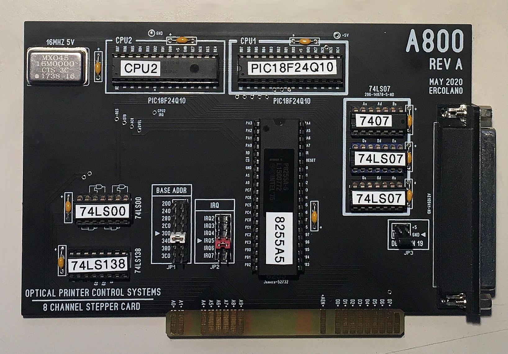
The A800 is an IBM PC compatible 8 channel stepper motor indexer board for ISA, ISA-16, and EISA slots.
The OPCS software uses this board to generate step/direction signals to stepper motor drives via the DB-37 connector.
 |
 |
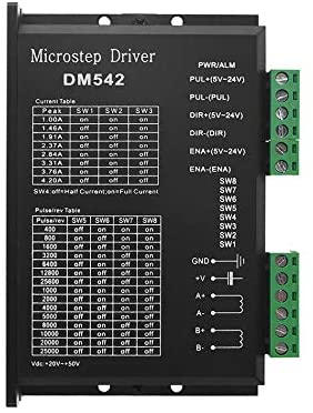 |
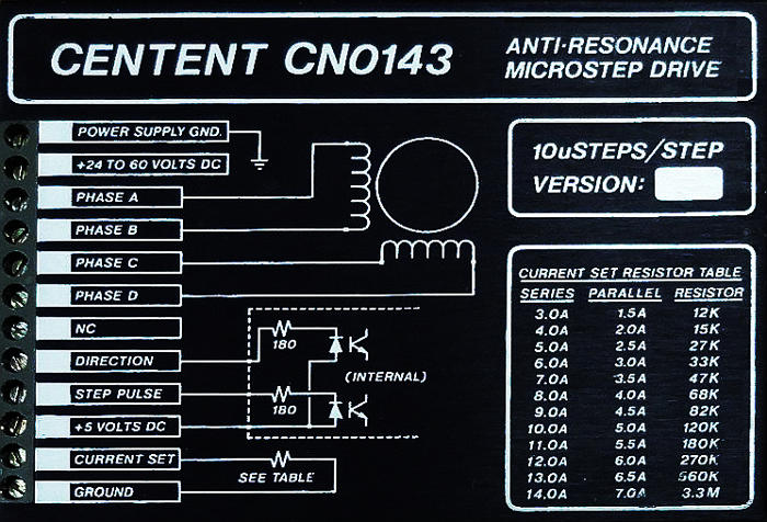
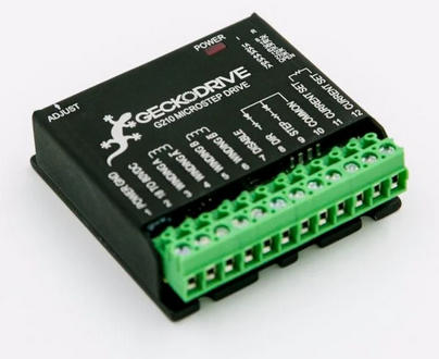
| Centent CNO-143 microstepper drive | Gecko 201 and 201X microstepping drives | Cost effective DM-542 microstepping drives |
OPCS software can make use of this board to control up to 8 motors by installing the A800DRV.COM DOS driver at boot time (via AUTOEXEC.BAT) which comes with the OPCS software installation.
The board's circuit design, gerber files, schematics, firmware, and DOS driver source code are all available below.
Currently there are only two revisions of this board, REV-A and REV-A1, which are identical except for small silk screen modifications, so the info below is mostly identical for both boards.
The A800DRV device driver assumes the default port of 0x0300h.
If this jumper is changed, the new port# must be passed to the driver so it knows how to initialize and communicate with the 8255 chip on its reassigned port. Normally this port# is not changed unless it conflicts with some other hardware.
|
Example: if the "Base Addr" jumper is set to 340, then the A800DRV.COM driver should be started with the "-b 340" command line flag, e.g.
|
Normally leave this at the default of "300".
Without any command line arguments, the A800DRV.COM program will default to this value.
If this jumper is changed, the new value must be passed to the A800DRV device driver so it knows which interrupt to monitor when feeding new motor values to the A800 card.
|
Example: if the "IRQ" jumper is set to IRQ6, then the A800DRV.COM driver should be started with the "-i" command line flag, e.g.
|
Normally leave this at the default of IRQ 5.
Without any command line arguments, the A800DRV.COM program will default to this value.
Normally leave this at the default of GND.
The outputs for DIR (direction) are logic hi (+5) for forward, and logic low (GND) for reverse.
The output signals can either be CMOS hi/low levels, or can be "open collector" (where logic 'hi' is 'open', and logic low is gnd). Which it is depends on the chips installed in the three chip positions to the left of the DB-37 connector on the A800 board, which can be populated with any of these chips:
        74HCT04 -- CMOS inverter high/low levels (typical)
        7404    -- TTL inverter high/low levels  (special purpose)
        74LS07  -- Open Collector                (special purpose)
For controlling the modern DM542 and FMD27400 motor drivers,
the 74HCT04 chips are recommended, and indeed for most drive applications that's the best.
The 74HCT04 chips have also been tested to work fine with Gecko, NextStep,
and Oriental Motor "Super Vexta" drives, using +5 as the common.
For Centent and Gecko drives, traditionally 74LS07 chips were used, e.g. in Kuper cards, and I think the Centent docs might recommend this.
While both chips work on all drives, analysis with an oscilloscope monitoring the stepper drive inputs may reveal one chip is better than the other for noise reduction. With 6' cables, 74HCT04 seems the best choice.
Always defer to the board's silk screen labelling, as the board designs may change since this document's writing (May 2020).
What follows are images of the different layers as they appear in Sprint6 Layout and/or a Geber viewer (such as the open source tool 'gerbv').
 A800 top and bottom layer | |
 A800 top layer |
 A800 bottom layer |
 A800 photo bottom side |
 A800 photo top side |
 Sheet 1 of 4 |
 Sheet 2 of 4 |
 Sheet 3 of 4 |
 Sheet 4 of 4 |
Release notes for the firmware are currently maintained in the header of the current a800-opcs-asm.asm file on github.
The precompiled .HEX file for the current REV-B2 firmware is here. (The older REV-A1 is no longer recommended, which is here.)
The .HEX file can be programmed onto PIC chips to create new A800 boards, or upgrade old ones.
I used Microchip's free MPLAB X IDE (v5.25) and their approx. $50 USB PIC PicKit4 programmer, but third party programmers also work.
The firmware was written in PIC assembly for speed and for critical step timing.
The circuit board is very simple hardware, so the "smarts" are all implemented in firmware.
The source code is managed as a GPL V.3 licensed project on github here: https://github.com/erco77/a800-opcs-pic-asm. The project uses tags for the different revision boards. Note that the firmware for "REV-A" also works for "REV-A1". This is because REV-A1 made no electrical changes. The assembly source code is generally not useful unless someone is trying to implement new features, apply a firmware fix, or wants to study in depth the low level operation of the board. The only useful thing to a casual reader might be the comments and README files.
The firmware design had to be extremely precise, with care taken to count every PIC instruction's execution time in clock cycles to ensure timing accuracy of the step pulses. This code is no walk in the park; besides being in assembly (which is hard enough to maintain), the critical timing requirements makes it extra hard to write, with loops unwound and NOP padded conditionals to ensure equal execution time for all conditions and states.
The code is modularized into separate .asm files to make it easy to maintain; unwinding loops causes redundant code, so having e.g. the A/B/C/D velocity loading code in separate .asm files makes it easy to compare the files with a tool like 'xxdiff' to clearly see diffs and detect typos.
The code can be compiled in "MPLAB X", Microchip's free Interactive Development Environment for their line of microcontrollers. It includes a C compiler and their own XC8 assembler. The code was originally conceived as a C program, but later rewritten in pure assembly to leverage the PIC's assembly level features, such as jump tables in place of switch() and if/else, low execution time branches, highly optimized array indexing, etc. There are references to the original C code in the assembly to make it easier to follow what's going on.
Once assembled into a .HEX file, it can then be programmed onto the PIC chip using a USB programmer, such as Microchip's PICKIT-3 or PICKIT-4 programmers, which are approx. $50 devices available from from companies like Digikey, Amazon, or direct from Microchip's online store.
Suffice it to say the firmware interacts with the IBM PC through the onboard 8255 interface chip, reading new velocities from the OPCS software that are buffered and fed to the motors on the next real time interrupt, and puts out a pulse stream to the final output buffer chips (either 74HCT04 inverters, or 7407 open collector outputs) that output to the DB-37 connector on the rear of the board.
The program is a TSR (Terminate Stay Resident) application written in 80x86 assembly, and attaches itself to software interrupt 0x99 (INT 099h) which is the API to the main application, and vectors hardware interrupt IRQ 5 to itself, which is triggered by the A800 card to request new velocities for each time sample.
The driver expects a 64k 'ring buffer' to be allocated by the main program to use for buffering velocities to be fed in realtime to the motors. The main program notifies the driver of the address of this buffer through the INT 099h API. The A800 board triggers IRQ5 at approx. 100Hz to feed velocities from the ringbuffer to the motors.
The program should be installed in memory on boot (via the AUTOEXEC.BAT file) so that it is present for use by OPCS via INT 099h.
The driver is based on older Kuper RTMC48 driver code I wrote back in the 1990s, but updated for the A800 card. The driver allocates a 20,000 byte 'environment' that needs to be common between OPCS and other external applications (e.g. HOME.EXE) so that they all agree on what the current motor max speeds and positions are, etc. The memory is allocated by the driver, and a pointer to it is returned by one of the INT 099h API calls. The main applications manage the data that is put into that buffer, so that e.g. counter values can be persistent when going in and out of OPCS applications.
The device driver source code is provided with a GPL v3 license, the API designed to work closely with the OPCS software, but can be used by other user applications as well (e.g. the HOME.EXE Program) to move the motors using the API, as described in device drivers docs.