=============================================
1A2 KSU BOARD - REV-B - 2 LINE / 4 EXTENSIONS
=============================================
erco@seriss.com - 1.0 (REV-A) Jan 16 2017
erco@seriss.com - 2.0 (REV-B) Jan 15 2018
erco@seriss.com - 2.1 (REV-B) Nov 24 2018 - Text + diagram improvements
If you find problems in this document, contact: erco@seriss.com
1.0 OVERVIEW OF THE 1A2 BOARD AND FEATURES
==========================================
This board allows one to attach up to 4 separate 1A2 "6 button" phones
for up to 2 separate telco lines, and provides these common 1A2 features
with simple "straight wiring":
o Up to 4 separate extensions
o 2 telco lines, each with Hold feature
o Lamps: o Blink when line is ringing
o On steady when in use
o Wink when on hold
o Intercom on line 5, with extension buzzing via touch-tone
o In a power outage, phones can still be used to dial out
o Handles remote hangups during hold (CPC signal from CO)
The intercom line provides extension buzzing via the TOUCH-TONE pad.
The user can pickup the intercom line and dial "1" thru "4" to buzz
the respective extensions, to signal the person at that extension
to pickup the intercom line and talk to the caller.
The system is also expandable: with a single board, the buzzer signals *REV-B*
for extra extensions 5 thru 8 can be brought out from the "BUZZ EXT5-8" *REV-B*
RJ11 connector to 66 blocks to provide buzzing on the extra 4 extensions *REV-B*
by dialing "5" thru "8" to reach EXT 5 thru EXT 8 respectively. *REV-B*
Also, with a second board and 66 blocks to handle wire assignment,
one can add an extra 2 extra telco lines on line 3 and 4, and can
provide a second intercom line (with its own buzzer signaling that
can either be separate, or merged with the existing buzzer signaling).
FEATURES / USER INSTRUCTIONS
============================
ANSWERING CALLS
---------------
When there's an incoming call, the lamp for that line will flash slowly on
all extensions, and any phones programmed to ring (with SW1/J1) for that
line will ring.
To take the call, press the slowly blinking line button and pickup
the handset. On all phones the blinking will stop for that line,
and the light will remain on, indicating the line is in use.
PUTTING CALLS ON HOLD
---------------------
To put a call on hold, press and release the Hold button. This will
put the call on hold, causing the lamp for that line to "wink" at a
fast rate, and the button for that line will release.
At this point you can take another call, or make another call,
or use the intercom line to signal someone to pick up the call on hold.
Any of the extensions can pick up the call on hold by pressing the
winking line button and pick up the phone. The winking will stop,
and the line's lamp will remain on when someone picks up the call.
MAKING CALLS
------------
Just press an inactive line button (the lamp is off), and pickup the
handset. You should hear a dialtone and can dial normally.
USING THE INTERCOM
------------------
The intercom is just like any other line, but it can only reach other
extensions. It does not use the phone company.
More than one person can pickup the intercom line to talk to each other.
The intercom line also supports 'buzzing' extensions using the Touch-Tone
pad, for instance to signal someone to pick up the intercom line to speak
to them.
To use the intercom to signal someone, press the intercom button (Line 5),
pickup the handset, and dial a digit on the dial pad. For instance, to
buzz the phone at extension #1, press "1" on the dial pad, and wait for
the person to pickup the intercom line.
The intercom line's lamp remains lit while it's in use.
NOTES:
o Intercom calls can't be put on Hold.
o Extensions have pre-programmed extension numbers. Usually people
tape a list of names and extension numbers, so that it's easy to
remember who's at what extension when using the buzzing feature.
o The intercom can also be wired to a public address system, so it
can be used for making general announcements. You should be able
to use any telephone hardware that can interface a Tip/Ring pair
to an amplifier, and attach it to Line #5 via a 66 block.
RECEPTIONIST
------------
In a business situation, a single receptionist might answer calls on the
various lines, and then either buzzes calls to the different extensions
via intercom, or can announce calls over a PA system.
Example use by a receptionist:
1) Line #1 rings, and its button flashes on and off at the slow
blinking rate (1 blink per second).
2) Receptionist presses the Line #1 button to answer the call
and determines who the caller wants to talk to.
3) Receptionist puts the call on Hold by pressing the Hold button.
The button's lamp now winks at the fast "on hold" rate (2 blinks
per second, or 120 IPM), indicating the call is on hold.
4) Pushes the intercom button, dials that person's extension.
When they pickup, tell them they have a call on line #1.
They push their Line #1 button, taking the call from hold.
5) Receptionist verifies they took the call by seeing the
Line#1 lamp change from flashing to steady, indicating
they took the call.
6) Receptionist hangs up.
In the case where the person at the extension doesn't answer, or answers but
can't take the call, the receptionist can return to the incoming call and
take a message.
PARTY LINE CONFERENCE CALLING
-----------------------------
We're sitting at extension #1, and are in progress with a call on Line #1.
We want to have the person at extension #3 included on the same call.
To do this:
1) Put the call on Hold by pressing the Hold button
2) Press Line #5 button (intercom) and Dial "3" to buzz extension #3
3) When extension #3 picks up, tell them to join the call on Line #1
4) They push the Line #1 button (taking the call from Hold)
5) We also push the Line #1 button to rejoin the call
6) Either extension can now leave the call.. the last person
to hang up ends the call.
Telephone companies have different limits on just how many phone extensions
can "party line" on the same call at a time.
2.x POWER FAILURE
=================
In the case of a local power failure, all the 1A2 phones can still be used
to access the telco phone lines (which run on their own power), and to
dial out to make calls.
Without power, the lamps won't light, the Hold feature won't work,
intercom won't work, and the phones won't ring for incomming calls.
For power failure ringing, one can (for example) have a separate
ringer, or a regular "home phone" attached to the telco line that
rings without separate power, to alert people when a call is coming
in.. and the 1A2 phones can be used to answer the call.
3.0 INSTALLATION
================
3.0.0 POWER REQUIREMENTS
------------------------
At minimum, the board needs a 12V 1amp regulated power supply.
For ringing, 90 VAC/20Hz power should also be supplied. Options
include:
* VIKING PS-48-RGA
* Ring generator from an old 1A2 KSU
* PowerDSINE 12v ring generator 70VAC/20Hz (can be powered
by the board's own 12v supply)
It's expected that at least one or more 1A2 multiline phones
are present, with ringers and buzzers wired as described below.
In the simplest configuration using straight ahead wiring by
plugging up to (4) 1A2 multiline phones (e.g. AT+T 2465) directly
into the on-board EXT1 - EXT4 50 pin connectors.
Wired this way, all phone extensions provide:
Telco on Line 1
Telco on Line 2
Intercom on Line 5
Lines 1 and 2 have per-extension programmable ringing via "SW1"
on the board.
Line 5 is the intercom line, and the tonepad can be used to buzz
any of the 4 extensions by number. e.g. dial "1" to buzz EXT 1.
For all extensions:
o Ringer is expected on the 20/45 pair (slt/yel, yel/slt)
o Buzzer is expected on the 17/42 pair (orn/yel, yel/orn)
3.1 RING PROGRAMMING
--------------------
SW1 on the board lets you program which of the extensions will ring
for incoming calls. Each extension phone can either not ring at all,
ring for only line1 calls, or only line2 calls, or both line1+2 calls.
Example ring programming for SW1:
_______________________________________________________________________________________________________
| Desired Ringing | SW1 Settings | Comments |
|===========================|=======================|===================================================|
| Ring all extensions | | If any extension should be able to hear |
| for incoming calls on | All switches "ON" | a call coming in on any line (like in a home). |
| Line1 or 2 | | In a business, this would be "night ringing". |
|---------------------------|-----------------------|---------------------------------------------------|
| Ring all extensions | 1,3,5,7 "ON" | Similar to the above, but not expecting incoming |
| for incoming calls ONLY | 2,4,6,8 "OFF" | calls on Line2 (e.g. if Line2 is a fax line, or |
| on Line1 | | is for outgoing calls only) |
|---------------------------|-----------------------|---------------------------------------------------|
| Ring only extension 1 | 1,2 "ON" | If only one phone should ring for incoming calls.|
| for incoming calls on | 3,4,5,6,7,8 "OFF" | In a business, a receptionist would sit at EXT1, |
| Line 1 and 2 | | and redirect calls via intercom buzzing. |
|---------------------------|-----------------------|---------------------------------------------------|
| Ring only extensions 1+2 | 1,3,6,8 "ON" | In a home, mom+dad have Line1, kids have Line2. |
| for Line 1, and extensions| 2,4,5,6 "OFF" | In a business, 2 departments each with their own |
| 3+4 for Line 2. | | dedicated lines. |
'---------------------------'-----------------------'---------------------------------------------------'
3.2 EXPANDED WIRING: ADDING EXTRA EXTENSIONS 5-8
------------------------------------------------
Up to 4 extra extensions (for a total of 8) can be used
by breaking out the EXT1 connector to 4 separate 66 blocks
as EXT5-8.
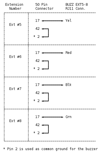
The "BUZZ EXT5-8" RJ11 connector provides 4 wires, one for each
of the extra extension buzzers, so that the extra extensions can
be buzzed via the TouchTone pad on the intercom line.
For this, the optional TIP125 transistors must be installed in
the "OPTIONAL EXTENSIONS" section of the board.
To wire the extra extensions, connect "EXT1" to a 66 block, and
parallel wire the needed 1A2 wire pairs for line 1,2 and 5 to the 66
blocks for the extra extensions 5 through 8.
Then separately patch a 4 conductor red/grn, blk/yel twisted pair
wire from the "BUZZ EXT5-8" RJ11 connector to the 66 block:
 For instance, breaking out extensions 5 and 6 would involve
a 66 block with dual RJ21 connectors used to add the extra
EXT5 and EXT6 off the EXT1 connector, just so you can separate
off the Y-O buzzer wire:
o Add bridge clips to carry lines 1, 2, 5 and bell + buzzer
across the connectors.
o Punch down lines 1, 2, 5 and bell + buzzer, with the exception
for the Y-O conductors for the buzzer being punched down to an
unused section of the 66 block (bottom 4 connections), and
to those Y-O wires, connect them to the appropriate wires from
the "BUZZER EXT5-8" RJ11 connector using:
Yellow -- for extension #5
Red -- for extension #6
Black -- for extension #7
Green -- for extension #8
4.0 ELECTRICAL DESCRIPTION
==========================
This section describes the electrical design considerations.
Refer to separate schematic and wiring diagrams for actual circuit layout.
4.1a Design Approach
--------------------
When desiging this 1A2 control circuit, one should first start with
circuits that need to work with the Central Office's (CO's) line:
o Detect ringing (for 1A2 lamps and ringers)
o Detect if a line is in use (for 1A2 lamps and hold)
o Remote hangup detection: "Calling Party Control" or CPC signals
o Holding a call
LDA-110 "AC input" optocouplers with darlington transistor outputs
are a perfect solution for detecting these:
Detect Ringing ("Ring Detect")
------------------------------
An optocoupler connected across Tip and Ring can be used to detect
the presence of AC ring voltage. With an appropriate R/C filter,
all low voltage AC and DC is rejected, detecting only the high
voltage AC ring voltage.
In such an arrangement, even an AC input optocoupler will briefly
turn off during the AC zero crossing transitions. For the purposes
of the 1A2 circuit, a pulse stretcher is used to keep the signal
active through the AC zero crossings of a ring, and turns off
only when the ring voltage has completely stopped.
Detect Line Use ("Line Detect")
-------------------------------
A series connected optocoupler can detect if the line is in use
by detecting current flow. If any call is in progress (or on
hold), current is flowing across Tip and Ring.
For our purposes, this signal is used to directly operate a DPDT
relay, (the "L" relay, as in "Line detect") so that two different
signals can be controlled during line detection:
1) Directs the Tip/Ring path to the Hold resistor
2) Directs the 1A2 extension lamps to either: Wink/Flash or be Off
CPC Detection
-------------
If the central office detects the calling party has hung up,
it briefly opens the Tip/Ring circuit, for about 1/2 a second.
This is useful mainly to free up a line if the call was on hold,
and the remote party hung up. The 1a2 system should drop the call
and free up the line.
The above "Line Detect" circuit will detect this; when current
stops flowing through Tip+Ring, the Line Detect signal will drop,
releasing the relay used to keep the hold resistor across the line.
Holding A Call
--------------
The CO detects a line is in use the same way we do; detecting the
presence of current flow across Tip and Ring.
To put a call "on hold", one only needs to shunt a low value resistor
across Tip and Ring, so that when the extension hangs up, the CO
still sees current flow, keeping the call in progress.
A 1A2 system flashes the lamps on the extensions while a call is
"on hold", connects a 120 ohm 1 watt resistor across the line to
achieve the needed current flow.
Both of these operations are often done with one or more mechanical
relays.
Next, the circuit design should consider 1A2 phone's inputs and
outputs.
Detecting The A Lead
--------------------
A 1A2 phone's only signal to control card is a simple switch closure
for the A lead.
When any extension's line button is down and the phone off hook,
the A lead for that line will be shorted to ground.
For line #1 this would be pins 27 and 2 (W-O/O-W) connected together.
For Line #2 this would be pins 30 and 2 (W-G/O-W) connected together.
For Line #3 this would be pins 33 and 2 (R-G/O-W) connected together.
For Line #4 this would be pins 36 and 2 (BK-BL/O-W) connected together.
For Line #5 this would be pins 39 and 2 (BK-BR/O-W) connected together.
Different circuits use this signal differently.
For our purposes, we have it control a single DPDT relay, the "A" relay,
so that this signal can trigger two different signals at once:
1) Directing Tip to either the 1A2 extensions or the Hold resistor
2) Directing 1A2 lamps to either: Wink/Flash/Off, or be On.
Making "ringing programmable" is an extra design goal.
1A2 phones have a separate wire pair just for the 70-105 VAC ringer
(pins 20/45) and a separte pair for the 10 VAC buzzer (pins 17/42).
Since we are in charge of ringing, the "ring detect" circuit needs
to do at least two things:
1) Flash the lamps for the line that's ringing, so the caller knows
which of the 5 lines needs to be answered
2) Ring the appropriate extension phone's bells (or buzzers)
The Bell System Practices (or BSP) recommends diodes be used to
"program" ringing, so that different extensions can ring depending
on which line is ringing.
In our case, we provide a full diode network, and use DIP switches
to direct the 90 VAC/30Hz ring signal. We also have a similar arrangement
to direct the 12 VAC/60Hz buzzer signal, if "buzzer ringing" is desired.
4.1 GENERAL BOARD LAYOUT
------------------------
The board is broken out into discrete sections, so that each can be
separately populated and debugged easily.
To access all feautures, 2 separate power supplies need to be provided:
12 VDC - for board logic and phone lamps
90 VAC - for phone ringing
90 VAC is optional if bell ringing isn't needed; phones can be 'rung'
using the 12VDC supply to signal buzzers in each phone.
Components for unused sections can be left unpopulated if need be.
Examples:
EXTRA EXTENSIONS 5-8
--------------------
If you won't be using the 'extra extensions' 5 through 8, you
can leave out all components in the dotted "EXTRA EXTENSIONS"
section, namely:
o The RJ11-4 female connector
o The 4 TIP125 "Buzzer Driver" transistors for
EXT5 through EXT8 in the BUZZER CONTROL section
LINE 2
------
If a Line2 isn't needed, all components can be left out of the
"LINE 2" section of the board:
o The RJ11-4 female connector
o The two relays and their protection diodes
o The two LDA110 optocouplers
o The 160 ohm resistor
o The 220uF capacitor
o The TIP125 "L2 LAMPS" transistor
o The leds for L and A relays
o The led for the IN USE indication
o All related resistors and capacitors
90 VAC RINGING
--------------
90VAC ringing is optional, since "ringing" can also be provided
by the buzzers using the BUZZ CALL section.
If 90VAC ringing won't be used, all components can be left out
of the "BELL CALL" section of the board, namely: the "90VAC
RINGER POW" connector, 8 diodes and 8 position DIP switch.
INTERCOM
--------
If intercom features aren't needed, all components can be
left out of the "ICM VOICE BATT", "INTERCOM DTMF DECODE",
and "INTERCOM POWER" sections.
BUZZERS
-------
If buzzers won't be used at all, either for intercom notifications
or incoming calls ("BUZZ CALL"), the 10K resistor network and
all the TIP125s in the BUZZ CONTROL section can be left out.
Also, the 8 diodes and DIP switch in the BUZZ CALL section can
be left out.
4.x 1A2 PHONES
--------------
Sometimes the internal wiring of the 1A2 phones have been
modified from the defaults based on the special needs of their last
installation. So before connecting up the phones, verify the phones
are wired "normally".
Usually the only wires that are changed are the buzzer and sometimes bell.
This board expects all phones to be internally wired the same way (if
plugging directly into the board), where:
o The phone's bell is wired to the 20/45 pair (yel/slt, slt/yel).
o The phone's buzzer is wired to the 17/42 pair (orn/yel, yel/orn).
For more info on the default internal wiring of 1A2 6 button phones, see:
http://seriss.com/people/erco/1a2/2564-pinout.html
The 1A2 6 button phones differ from regular phones in the following way:
A 50 pin cable instead of a single wire pair. This is because 1A2
phones are capable of accessing any of 5 lines, and include additional
control signals regular phones don't have; lamps, switch closures,
bell and buzzer options.
The 5 line buttons each have a 10VAC lamp, a separate wire pair
for each. With this 1A2 card, 12VDC is used to run the lamps,
which at that voltage is around ~42 mA per lamp. So with a max
of 4 phone sets, if Lines 1, 2 and 5 are all lit at the same time,
that's (3 x 4 x 42mA) = 504mA current draw for just the lamps.
When a button is down and the receiver is lifted, that button's
switch closes the "A lead" pair for that line. The KSU board uses
this switch closure for logic to handle its internal logic.
The "bell" (ringer), which singals people there's an incoming
call, has its own separate wire pair, and is NOT connected in
any way to any of the Tip/Ring pairs. It needs a separate 90VAC
supply to ring the phone's bell. This is because ringing can be
programmed at the KSU to ring for more than one line, and ringing
can happen while someone's already on a call.
The "buzzer", used for intercom signalling, has a separate wire
pair and runs on 18VAC. With this board, 12VDC at 60Hz is used.
Other than that, the internals of the phone are mostly the same as
the old home phone sets; there's a voice hybrid, a switch hook,
a carbon-mic based handset, a touchtone dial.
4.2 TELCO LINE
--------------
In the following description, voltages are approximate and vary by location.
The lines from the telephone company idle at 48 VDC.
Incoming calls presents 90VAC/20Hz on the line.
When someone picks up the call, the phone's hybrid presents a current draw
sensed by the phone company, which switches to a 6 VDC talk voltage that powers
the talk circuit of the phone.
4.3 CIRCUIT DESCRIPTION
-----------------------
Electronics are used to achieve the various needs of a 1A2 phone system:
o Controls lamps, bells, buzzers on the phones to give visual
and audio feedback.
o Manages line state detection and Hold functions
o Provides a local intercom system, including Touch-Tone buzzing
of extensions.
Simple circuitry is used to achive this; optocouplers (LDA-110),
DPST 12 volt relays (DS2Y-S-12VDC), linear comparitors (LM339),
power transistors to control lamps and buzzers (TIP125), and some
DTMF circuitry (MT8870, 7445).
Linear comparitors are employed to serve a variety of functions..
they are used as inverters, "relaxation oscillators", logic gates,
signal converters, isolation gates.
By design, no computers or software is used in this circuit.
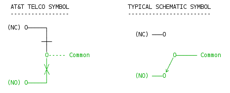
To understand the schematics, one needs to understand the phone
company's unusual relay symbols; this is a single pair of
Normally Open (NO) and Normally Closed (NC) RELAY TERMINALS
with a Common (C) connection:
For instance, breaking out extensions 5 and 6 would involve
a 66 block with dual RJ21 connectors used to add the extra
EXT5 and EXT6 off the EXT1 connector, just so you can separate
off the Y-O buzzer wire:
o Add bridge clips to carry lines 1, 2, 5 and bell + buzzer
across the connectors.
o Punch down lines 1, 2, 5 and bell + buzzer, with the exception
for the Y-O conductors for the buzzer being punched down to an
unused section of the 66 block (bottom 4 connections), and
to those Y-O wires, connect them to the appropriate wires from
the "BUZZER EXT5-8" RJ11 connector using:
Yellow -- for extension #5
Red -- for extension #6
Black -- for extension #7
Green -- for extension #8
4.0 ELECTRICAL DESCRIPTION
==========================
This section describes the electrical design considerations.
Refer to separate schematic and wiring diagrams for actual circuit layout.
4.1a Design Approach
--------------------
When desiging this 1A2 control circuit, one should first start with
circuits that need to work with the Central Office's (CO's) line:
o Detect ringing (for 1A2 lamps and ringers)
o Detect if a line is in use (for 1A2 lamps and hold)
o Remote hangup detection: "Calling Party Control" or CPC signals
o Holding a call
LDA-110 "AC input" optocouplers with darlington transistor outputs
are a perfect solution for detecting these:
Detect Ringing ("Ring Detect")
------------------------------
An optocoupler connected across Tip and Ring can be used to detect
the presence of AC ring voltage. With an appropriate R/C filter,
all low voltage AC and DC is rejected, detecting only the high
voltage AC ring voltage.
In such an arrangement, even an AC input optocoupler will briefly
turn off during the AC zero crossing transitions. For the purposes
of the 1A2 circuit, a pulse stretcher is used to keep the signal
active through the AC zero crossings of a ring, and turns off
only when the ring voltage has completely stopped.
Detect Line Use ("Line Detect")
-------------------------------
A series connected optocoupler can detect if the line is in use
by detecting current flow. If any call is in progress (or on
hold), current is flowing across Tip and Ring.
For our purposes, this signal is used to directly operate a DPDT
relay, (the "L" relay, as in "Line detect") so that two different
signals can be controlled during line detection:
1) Directs the Tip/Ring path to the Hold resistor
2) Directs the 1A2 extension lamps to either: Wink/Flash or be Off
CPC Detection
-------------
If the central office detects the calling party has hung up,
it briefly opens the Tip/Ring circuit, for about 1/2 a second.
This is useful mainly to free up a line if the call was on hold,
and the remote party hung up. The 1a2 system should drop the call
and free up the line.
The above "Line Detect" circuit will detect this; when current
stops flowing through Tip+Ring, the Line Detect signal will drop,
releasing the relay used to keep the hold resistor across the line.
Holding A Call
--------------
The CO detects a line is in use the same way we do; detecting the
presence of current flow across Tip and Ring.
To put a call "on hold", one only needs to shunt a low value resistor
across Tip and Ring, so that when the extension hangs up, the CO
still sees current flow, keeping the call in progress.
A 1A2 system flashes the lamps on the extensions while a call is
"on hold", connects a 120 ohm 1 watt resistor across the line to
achieve the needed current flow.
Both of these operations are often done with one or more mechanical
relays.
Next, the circuit design should consider 1A2 phone's inputs and
outputs.
Detecting The A Lead
--------------------
A 1A2 phone's only signal to control card is a simple switch closure
for the A lead.
When any extension's line button is down and the phone off hook,
the A lead for that line will be shorted to ground.
For line #1 this would be pins 27 and 2 (W-O/O-W) connected together.
For Line #2 this would be pins 30 and 2 (W-G/O-W) connected together.
For Line #3 this would be pins 33 and 2 (R-G/O-W) connected together.
For Line #4 this would be pins 36 and 2 (BK-BL/O-W) connected together.
For Line #5 this would be pins 39 and 2 (BK-BR/O-W) connected together.
Different circuits use this signal differently.
For our purposes, we have it control a single DPDT relay, the "A" relay,
so that this signal can trigger two different signals at once:
1) Directing Tip to either the 1A2 extensions or the Hold resistor
2) Directing 1A2 lamps to either: Wink/Flash/Off, or be On.
Making "ringing programmable" is an extra design goal.
1A2 phones have a separate wire pair just for the 70-105 VAC ringer
(pins 20/45) and a separte pair for the 10 VAC buzzer (pins 17/42).
Since we are in charge of ringing, the "ring detect" circuit needs
to do at least two things:
1) Flash the lamps for the line that's ringing, so the caller knows
which of the 5 lines needs to be answered
2) Ring the appropriate extension phone's bells (or buzzers)
The Bell System Practices (or BSP) recommends diodes be used to
"program" ringing, so that different extensions can ring depending
on which line is ringing.
In our case, we provide a full diode network, and use DIP switches
to direct the 90 VAC/30Hz ring signal. We also have a similar arrangement
to direct the 12 VAC/60Hz buzzer signal, if "buzzer ringing" is desired.
4.1 GENERAL BOARD LAYOUT
------------------------
The board is broken out into discrete sections, so that each can be
separately populated and debugged easily.
To access all feautures, 2 separate power supplies need to be provided:
12 VDC - for board logic and phone lamps
90 VAC - for phone ringing
90 VAC is optional if bell ringing isn't needed; phones can be 'rung'
using the 12VDC supply to signal buzzers in each phone.
Components for unused sections can be left unpopulated if need be.
Examples:
EXTRA EXTENSIONS 5-8
--------------------
If you won't be using the 'extra extensions' 5 through 8, you
can leave out all components in the dotted "EXTRA EXTENSIONS"
section, namely:
o The RJ11-4 female connector
o The 4 TIP125 "Buzzer Driver" transistors for
EXT5 through EXT8 in the BUZZER CONTROL section
LINE 2
------
If a Line2 isn't needed, all components can be left out of the
"LINE 2" section of the board:
o The RJ11-4 female connector
o The two relays and their protection diodes
o The two LDA110 optocouplers
o The 160 ohm resistor
o The 220uF capacitor
o The TIP125 "L2 LAMPS" transistor
o The leds for L and A relays
o The led for the IN USE indication
o All related resistors and capacitors
90 VAC RINGING
--------------
90VAC ringing is optional, since "ringing" can also be provided
by the buzzers using the BUZZ CALL section.
If 90VAC ringing won't be used, all components can be left out
of the "BELL CALL" section of the board, namely: the "90VAC
RINGER POW" connector, 8 diodes and 8 position DIP switch.
INTERCOM
--------
If intercom features aren't needed, all components can be
left out of the "ICM VOICE BATT", "INTERCOM DTMF DECODE",
and "INTERCOM POWER" sections.
BUZZERS
-------
If buzzers won't be used at all, either for intercom notifications
or incoming calls ("BUZZ CALL"), the 10K resistor network and
all the TIP125s in the BUZZ CONTROL section can be left out.
Also, the 8 diodes and DIP switch in the BUZZ CALL section can
be left out.
4.x 1A2 PHONES
--------------
Sometimes the internal wiring of the 1A2 phones have been
modified from the defaults based on the special needs of their last
installation. So before connecting up the phones, verify the phones
are wired "normally".
Usually the only wires that are changed are the buzzer and sometimes bell.
This board expects all phones to be internally wired the same way (if
plugging directly into the board), where:
o The phone's bell is wired to the 20/45 pair (yel/slt, slt/yel).
o The phone's buzzer is wired to the 17/42 pair (orn/yel, yel/orn).
For more info on the default internal wiring of 1A2 6 button phones, see:
http://seriss.com/people/erco/1a2/2564-pinout.html
The 1A2 6 button phones differ from regular phones in the following way:
A 50 pin cable instead of a single wire pair. This is because 1A2
phones are capable of accessing any of 5 lines, and include additional
control signals regular phones don't have; lamps, switch closures,
bell and buzzer options.
The 5 line buttons each have a 10VAC lamp, a separate wire pair
for each. With this 1A2 card, 12VDC is used to run the lamps,
which at that voltage is around ~42 mA per lamp. So with a max
of 4 phone sets, if Lines 1, 2 and 5 are all lit at the same time,
that's (3 x 4 x 42mA) = 504mA current draw for just the lamps.
When a button is down and the receiver is lifted, that button's
switch closes the "A lead" pair for that line. The KSU board uses
this switch closure for logic to handle its internal logic.
The "bell" (ringer), which singals people there's an incoming
call, has its own separate wire pair, and is NOT connected in
any way to any of the Tip/Ring pairs. It needs a separate 90VAC
supply to ring the phone's bell. This is because ringing can be
programmed at the KSU to ring for more than one line, and ringing
can happen while someone's already on a call.
The "buzzer", used for intercom signalling, has a separate wire
pair and runs on 18VAC. With this board, 12VDC at 60Hz is used.
Other than that, the internals of the phone are mostly the same as
the old home phone sets; there's a voice hybrid, a switch hook,
a carbon-mic based handset, a touchtone dial.
4.2 TELCO LINE
--------------
In the following description, voltages are approximate and vary by location.
The lines from the telephone company idle at 48 VDC.
Incoming calls presents 90VAC/20Hz on the line.
When someone picks up the call, the phone's hybrid presents a current draw
sensed by the phone company, which switches to a 6 VDC talk voltage that powers
the talk circuit of the phone.
4.3 CIRCUIT DESCRIPTION
-----------------------
Electronics are used to achieve the various needs of a 1A2 phone system:
o Controls lamps, bells, buzzers on the phones to give visual
and audio feedback.
o Manages line state detection and Hold functions
o Provides a local intercom system, including Touch-Tone buzzing
of extensions.
Simple circuitry is used to achive this; optocouplers (LDA-110),
DPST 12 volt relays (DS2Y-S-12VDC), linear comparitors (LM339),
power transistors to control lamps and buzzers (TIP125), and some
DTMF circuitry (MT8870, 7445).
Linear comparitors are employed to serve a variety of functions..
they are used as inverters, "relaxation oscillators", logic gates,
signal converters, isolation gates.
By design, no computers or software is used in this circuit.
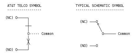
To understand the schematics, one needs to understand the phone
company's unusual relay symbols; this is a single pair of
Normally Open (NO) and Normally Closed (NC) RELAY TERMINALS
with a Common (C) connection:
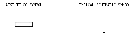
 ..and the RELAY COIL is represented this way:
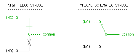
 So when the relay is OFF, current flows through the circuit this way,
as shown in green:
So when the relay is OFF, current flows through the circuit this way,
as shown in green:
 ..and when the relay is ON, current flows through the circuit this way,
as shown in green:
..and when the relay is ON, current flows through the circuit this way,
as shown in green:
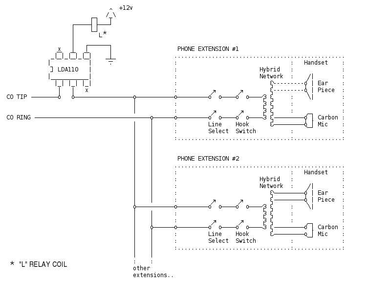
 4.3.1 - Phone Lines: Tip and Ring
---------------------------------
The circuit senses the telephone line for signals from the central
office (CO) and the local phone extensions (EXT) or 'stations' (STA).
Optocouplers are used to sense the phone line "tip" and "ring" pair;
one senses if the line is in use ("Line Detect"), the other senses
ring voltage if there's an incoming call ("Ring Detect").
Since the board supports two incoming lines, there's a separate pair
of optocouplers to sense these states for each line.
4.3.1.1 LINE SENSE CIRCUIT
--------------------------
The board needs to be able to detect when a line is in use for
two purposes:
o To light the line's lamp indicating the line is in use
o Break a call out of "Hold" if the remote hangs up
For this, a single optocoupler is connected in series with
the line to detect current flow through the phone hybrids
or the hold resistor (if a call is on hold).
An LDA-110 optocoupler can pass AC or DC through them, due
to the use of back-to-back LEDs on the input. In this way
it can detect current flow without affecting the call.
When phones are not in use (hung up) and no calls are on hold,
there is no current flow across Tip/Ring, so the optocoupler's
LEDs (on the LDA110's) are both off.
When one or more phones are off-hook for a line, or a line is
on Hold, the "Line Sense" optocoupler operates, presenting a
grounded output at pin 5, which directly powers the Line Sense
"L" relay.
4.3.1 - Phone Lines: Tip and Ring
---------------------------------
The circuit senses the telephone line for signals from the central
office (CO) and the local phone extensions (EXT) or 'stations' (STA).
Optocouplers are used to sense the phone line "tip" and "ring" pair;
one senses if the line is in use ("Line Detect"), the other senses
ring voltage if there's an incoming call ("Ring Detect").
Since the board supports two incoming lines, there's a separate pair
of optocouplers to sense these states for each line.
4.3.1.1 LINE SENSE CIRCUIT
--------------------------
The board needs to be able to detect when a line is in use for
two purposes:
o To light the line's lamp indicating the line is in use
o Break a call out of "Hold" if the remote hangs up
For this, a single optocoupler is connected in series with
the line to detect current flow through the phone hybrids
or the hold resistor (if a call is on hold).
An LDA-110 optocoupler can pass AC or DC through them, due
to the use of back-to-back LEDs on the input. In this way
it can detect current flow without affecting the call.
When phones are not in use (hung up) and no calls are on hold,
there is no current flow across Tip/Ring, so the optocoupler's
LEDs (on the LDA110's) are both off.
When one or more phones are off-hook for a line, or a line is
on Hold, the "Line Sense" optocoupler operates, presenting a
grounded output at pin 5, which directly powers the Line Sense
"L" relay.
 The "L" relay operates whenever the line is in use, either
when one or more extensions are offhook, or if a call is on hold.
When the "L" Line Sense DPDT relay *operates*, the relay's two
internal switches each handles separate things:
o Provides a possible path to 12V to control the phone extension's
lamps (Depending on the state of the "A" relay)
o Provides a possible path for Tip/Ring to the Hold Resistor,
putting the call on Hold. (Depending on the state of the "A" relay)
When the "L" relay is *idle*, the relay's two internal switches
each handles separate things:
o Provides a possible path that turns off the phone extension's
lamps, or provides a path to an alternating 1 Hz signal that
can flash the lamps indicating an incoming call, depending
on the state of the "A" relay and the combination of the
"RING DETECT" and "RING STRETCH" circuit.
o Prevents any possible path to the Hold resistor between
Tip/Ring. (Depending on the state of the "A" relay)
So the "L" relay follows the "Line Sense" optocoupler,
and the "A" relay follows the A lead.. that being the state
of all buttons for a particular line, connected in series.
The "A" relay operates whenever a button is pressed and the
phone for that extension is offhook. The A lead opens
when someone hangs up or presses down on the Hold button.
4.3.1.2 RING DETECTION
----------------------
While idle, the LDA110 "Ring Detect" optocoupler is off,
providing an open output on pin #5.
This output is pulled high by a 50K resistor, which after
passing through a small noise-rejecting RC circuit, causing
the inputs on two LM339 comparitors high, causing their outputs
to both open:
1) One comparitor's output controls a 2n3906 transistor
which in turn controls a relay C. When the comparitor's
output is open, the transistor is off, the relay is off,
so no ringing is supplied.
2) The other comparitor driving the "Ring Stretch" circuit
will be off, leaving the Ring Flash (RIFL) output open,
which by way of the contacts on relays L and A, provides
an open circuit to the base of the lamp control transistor
(TIP125-L1) off, causing all lamps to be off for that line.
When a call arrives, ~90VAC arrives on the T/R pair from the
Central Office (CO), which lights the LEDs in the "RING DETECT"
optocoupler through a series resistor/capacitor across the line.
While ringing is happening, the optocoupler provides a grounded
output on pin 5, driving the inputs of both downstream LM339's
comparitor's outputs low, which:
1) Turns on the 2n3906 transistor in the "INCOMING CALL" circuit,
turning on that line's ring relay for the duration of the AC
ring voltage.
This relay's contacts provide either 90VAC to drive the ringers
on extensions programmed for ringing on that line, or provides
a path from the "BUZZ OSCILLATOR" circuit's 60Hz 12v
ground signal to buzz any buzzers programmed for ringing
via the power transistors in the "BUZZER CONTROL" circuit.
In either case, the ringing/buzzing directly follows the
telco ringing.
2) Triggers the RING STRETCH circuit, passing the 1 Hz flashing
from the "RING OSCILLATOR" to reach the RIFL input on the
L and A relays.
This 1 Hz flashing signal continues to run during and between
telco ring bursts, ensuring the lamps continue to flash between
rings.
When ringing from the telco stops, the 1 Hz flashing will continue
for up to 7 seconds.
4.3.2 HOLD CIRCUIT
------------------
When a phone call is active, the "L" relay and "A" relay are
both operating, because:
o The "Line Sense" optocoupler is operating due to constant
current flow detected through the phone's hybrid
o The "A" lead is grounded by the phone's line button being down.
When someone presses Hold, the A lead signal is interrupted, pulling
ground from the A relay's coil, turning the relay off. But the phone's
hybrid is still across the line, so the LINE DETECT circuit continues
to see current, keeping the L relay operated.
This combination (A relay off, L relay on) causes the logic of the two
relays to:
o Connect the "Hold Resistor" across the Station Tip/Ring pair,
holding the line, keeping current flowing, and thus keeping
the LINE DETECT circuit and L relay operating.
o Connects the "Hold Lamp Oscillator" to the TIP125-L transistor,
winking the lamps for that line at the 2 Hz rate.
When the Hold button is released, the line button pops up, disconnecting
the phone's hybrid from Tip/Ring.
Because the "Hold Resistor" is now shunted across the line, the
"LINE SENSE" optocoupler and L relay remain operating.
"A" RELAY DELAY:
The 220uF capacitor across the A relay's coil holds the A
relay operating an extra few milliseconds when the A lead
opens to prevent a "false hold" condition. This small delay
ensures a quick hangup won't be mistaken for Hold.
The hook switch on the phone is configured to first open
Tip/Ring before opening the A lead, to prevent a false
hold. One can see this if one hangs up slowly; first the
"L" relay turns off, then the "A" relay.
4.3.3 LAMP CIRCUIT
------------------
The phone's lamps are incandescent bulbs that were designed to
run properly at ~10 VAC.
In this system, the lamps are run by 12 VDC, and consume approx
40mA per lamp. So a 4 extension system may use approx 160mA per
line (e.g. when Line #1 is in use, all 4 extension's lamps for
Line #1 will be lit).
If the extra 4 extensions are used, a total of 8 extensions
would use up to 320mA.
The TIP125 power transistor, which is turned on when its
input is grounded, can handle that with very minor heating.
Beyond that, a heat sink is recommended, or a TIP32 transistor
with a 1K base resistor can be substituted for the TIP125 / 10K
resistor.
The lamps have 4 possible states:
o Off (Idle)
o Ring flash (line ringing)
o Hold wink (line on hold)
o Continuous on (line in use)
The combined logic of the two relays "A" and "L" control which of these
4 possible states are active at any given time.
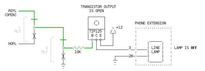
Idle.
-----
When the line is idle, the relays are off, connecting the
TIP125 transistor directly to the "RIFL" output of the
"RING STRETCH" LM339:
o For Line 1 that would be pin 2 of LM339-B.
o For Line 2 that would be pin 2 of LM339-C.
The RIFL output remains "open" when there's no ringing,
so the TIP125 transistor remains off, and thus all the
line lamps will be off. The TIP125 has internal pullups
that keep the base at +12, leaving the collector output
open (off).
The effective +12VDC current flow path is shown in GREEN:
The "L" relay operates whenever the line is in use, either
when one or more extensions are offhook, or if a call is on hold.
When the "L" Line Sense DPDT relay *operates*, the relay's two
internal switches each handles separate things:
o Provides a possible path to 12V to control the phone extension's
lamps (Depending on the state of the "A" relay)
o Provides a possible path for Tip/Ring to the Hold Resistor,
putting the call on Hold. (Depending on the state of the "A" relay)
When the "L" relay is *idle*, the relay's two internal switches
each handles separate things:
o Provides a possible path that turns off the phone extension's
lamps, or provides a path to an alternating 1 Hz signal that
can flash the lamps indicating an incoming call, depending
on the state of the "A" relay and the combination of the
"RING DETECT" and "RING STRETCH" circuit.
o Prevents any possible path to the Hold resistor between
Tip/Ring. (Depending on the state of the "A" relay)
So the "L" relay follows the "Line Sense" optocoupler,
and the "A" relay follows the A lead.. that being the state
of all buttons for a particular line, connected in series.
The "A" relay operates whenever a button is pressed and the
phone for that extension is offhook. The A lead opens
when someone hangs up or presses down on the Hold button.
4.3.1.2 RING DETECTION
----------------------
While idle, the LDA110 "Ring Detect" optocoupler is off,
providing an open output on pin #5.
This output is pulled high by a 50K resistor, which after
passing through a small noise-rejecting RC circuit, causing
the inputs on two LM339 comparitors high, causing their outputs
to both open:
1) One comparitor's output controls a 2n3906 transistor
which in turn controls a relay C. When the comparitor's
output is open, the transistor is off, the relay is off,
so no ringing is supplied.
2) The other comparitor driving the "Ring Stretch" circuit
will be off, leaving the Ring Flash (RIFL) output open,
which by way of the contacts on relays L and A, provides
an open circuit to the base of the lamp control transistor
(TIP125-L1) off, causing all lamps to be off for that line.
When a call arrives, ~90VAC arrives on the T/R pair from the
Central Office (CO), which lights the LEDs in the "RING DETECT"
optocoupler through a series resistor/capacitor across the line.
While ringing is happening, the optocoupler provides a grounded
output on pin 5, driving the inputs of both downstream LM339's
comparitor's outputs low, which:
1) Turns on the 2n3906 transistor in the "INCOMING CALL" circuit,
turning on that line's ring relay for the duration of the AC
ring voltage.
This relay's contacts provide either 90VAC to drive the ringers
on extensions programmed for ringing on that line, or provides
a path from the "BUZZ OSCILLATOR" circuit's 60Hz 12v
ground signal to buzz any buzzers programmed for ringing
via the power transistors in the "BUZZER CONTROL" circuit.
In either case, the ringing/buzzing directly follows the
telco ringing.
2) Triggers the RING STRETCH circuit, passing the 1 Hz flashing
from the "RING OSCILLATOR" to reach the RIFL input on the
L and A relays.
This 1 Hz flashing signal continues to run during and between
telco ring bursts, ensuring the lamps continue to flash between
rings.
When ringing from the telco stops, the 1 Hz flashing will continue
for up to 7 seconds.
4.3.2 HOLD CIRCUIT
------------------
When a phone call is active, the "L" relay and "A" relay are
both operating, because:
o The "Line Sense" optocoupler is operating due to constant
current flow detected through the phone's hybrid
o The "A" lead is grounded by the phone's line button being down.
When someone presses Hold, the A lead signal is interrupted, pulling
ground from the A relay's coil, turning the relay off. But the phone's
hybrid is still across the line, so the LINE DETECT circuit continues
to see current, keeping the L relay operated.
This combination (A relay off, L relay on) causes the logic of the two
relays to:
o Connect the "Hold Resistor" across the Station Tip/Ring pair,
holding the line, keeping current flowing, and thus keeping
the LINE DETECT circuit and L relay operating.
o Connects the "Hold Lamp Oscillator" to the TIP125-L transistor,
winking the lamps for that line at the 2 Hz rate.
When the Hold button is released, the line button pops up, disconnecting
the phone's hybrid from Tip/Ring.
Because the "Hold Resistor" is now shunted across the line, the
"LINE SENSE" optocoupler and L relay remain operating.
"A" RELAY DELAY:
The 220uF capacitor across the A relay's coil holds the A
relay operating an extra few milliseconds when the A lead
opens to prevent a "false hold" condition. This small delay
ensures a quick hangup won't be mistaken for Hold.
The hook switch on the phone is configured to first open
Tip/Ring before opening the A lead, to prevent a false
hold. One can see this if one hangs up slowly; first the
"L" relay turns off, then the "A" relay.
4.3.3 LAMP CIRCUIT
------------------
The phone's lamps are incandescent bulbs that were designed to
run properly at ~10 VAC.
In this system, the lamps are run by 12 VDC, and consume approx
40mA per lamp. So a 4 extension system may use approx 160mA per
line (e.g. when Line #1 is in use, all 4 extension's lamps for
Line #1 will be lit).
If the extra 4 extensions are used, a total of 8 extensions
would use up to 320mA.
The TIP125 power transistor, which is turned on when its
input is grounded, can handle that with very minor heating.
Beyond that, a heat sink is recommended, or a TIP32 transistor
with a 1K base resistor can be substituted for the TIP125 / 10K
resistor.
The lamps have 4 possible states:
o Off (Idle)
o Ring flash (line ringing)
o Hold wink (line on hold)
o Continuous on (line in use)
The combined logic of the two relays "A" and "L" control which of these
4 possible states are active at any given time.
Idle.
-----
When the line is idle, the relays are off, connecting the
TIP125 transistor directly to the "RIFL" output of the
"RING STRETCH" LM339:
o For Line 1 that would be pin 2 of LM339-B.
o For Line 2 that would be pin 2 of LM339-C.
The RIFL output remains "open" when there's no ringing,
so the TIP125 transistor remains off, and thus all the
line lamps will be off. The TIP125 has internal pullups
that keep the base at +12, leaving the collector output
open (off).
The effective +12VDC current flow path is shown in GREEN:
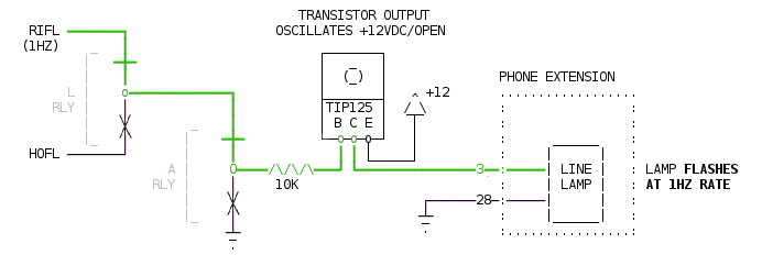
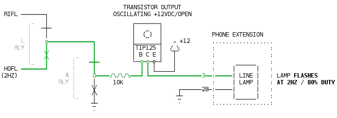
 Ringing.
--------
When the line starts ringing, the L and A relays remain off
(same as idle), continuing to connect the TIP125 to the "RIFL"
output of the RING STRETCH circuit.
But due to the presence of ringing, the RIFL signal starts
oscillating, alternating from open/ground at a 1Hz rate,
turning the transistor on and off, which flashes all the
line lamps, giving a visual indication which line is ringing.
The effective connection path of an OSCILATING 1HZ signal
(transitioning between +12VDC and an open circuit) is shown
below in GREEN:
Ringing.
--------
When the line starts ringing, the L and A relays remain off
(same as idle), continuing to connect the TIP125 to the "RIFL"
output of the RING STRETCH circuit.
But due to the presence of ringing, the RIFL signal starts
oscillating, alternating from open/ground at a 1Hz rate,
turning the transistor on and off, which flashes all the
line lamps, giving a visual indication which line is ringing.
The effective connection path of an OSCILATING 1HZ signal
(transitioning between +12VDC and an open circuit) is shown
below in GREEN:
 Hold.
-----
When the line is on hold, the L relay is operating, the A
relay is off, and together these present the input of the
TIP125 transistor to the HOFL oscillator, which alternates
between open and gnd at a 2Hz 80% duty cycle rate, causing
all lamps for that line to "wink" at 2 Hz.
The effective connection path is shown in GREEN:
Hold.
-----
When the line is on hold, the L relay is operating, the A
relay is off, and together these present the input of the
TIP125 transistor to the HOFL oscillator, which alternates
between open and gnd at a 2Hz 80% duty cycle rate, causing
all lamps for that line to "wink" at 2 Hz.
The effective connection path is shown in GREEN:
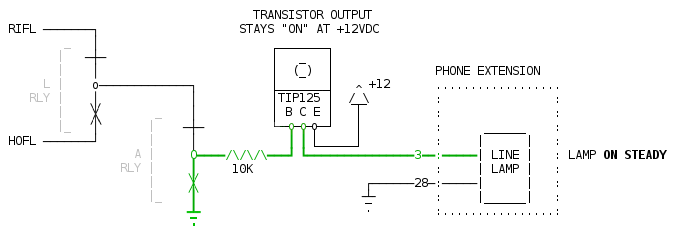
 In Use.
-------
When the line is in use, the A/L relays are both operating,
the A relay's contacts connect the TIP125 transistor's B input
directly to GND, which turns on all the lamps for that line.
The effective connection path is shown in GREEN:
In Use.
-------
When the line is in use, the A/L relays are both operating,
the A relay's contacts connect the TIP125 transistor's B input
directly to GND, which turns on all the lamps for that line.
The effective connection path is shown in GREEN:
 4.3.4 RING PROGRAMMING
----------------------
When a line is ringing, the output of the "RING DETECT" circuit
drives an LM339 buffer (e.g. LM339-B4) to ground (schematic Pg#1),
operating the "C" relay's 2N3906 transistor to go high during each
ring burst, operating the "C" relay in the INCOMING CALL circuit
(schematic Pg#3).
The relay operates while ring voltage is present, so it opens
and closes on each ring, passing the AC RING voltage to the
phone ringers that have been programmed to ring via the SW2
DIP switches.
This board supports two kinds of ringing for incoming calls,
each type handled by separate terminals on the C relay:
o "Bell" calling to ring the phone's bells.
This needs an external 90vac/30Hz ring generator.
o "Buzz" calling to buzz the phone's buzzers.
Uses built in 12v supply to buzz the phone's buzzers.
Bell Calling
------------
The contacts of the "C" relay connect 90VAC is then directed
through a matrix of diodes and DIP switches which allow the
installer to "program" which lines ring when a call comes in
via the switch settings.
The diode network prevent back currents, enabling the programming,
but looses 1/2 of the AC wave used for ringing. This is normal
on 1A2 systems, which are designed for either 1/2 cycle or full
cycle ringing.
When the ring relay is energized, the locally provided 90 VAC
ring voltage is directed to the STA RG / STA RR pins on that
extension. Assuming the phone's extension has a ringer wired
across those pins, the phone will ring.
TRANSISTOR CIRCUIT CONTROLLING "C RELAY" COIL
=============================================
┏━━━━━━━┓
┃ 2n3906┃
┃ ┃
+12 ʌ ┃ E B C ┃
╱ ╲ ┗━┳━┳━┳━┛
▔┃▔ ┃ ┃ ┃ ┏━┓
____ ┗━━━━━━━┛ ┃ ┗━━━━━┫ ┣━━━━━━┓
RDET ┃ ┗━┛ ━┻━
━━━━━━━━━^⌄^⌄^⌄━━━━┛ C ▔
1K Relay
"C RELAY" RINGER CIRCUIT
========================
................................................ ..................
: : : :
: : Amphenol : :
: : Pin# : :
: ▁▁▁▁▁▁▁▁ : : ▁▁▁▁▁▁▁▁ :
: (N.C.) ┃ ┃ : : ┃ ┃ :
: ▁▁▁▁▁▁▁┃▁▁▁▁▁▁▁▁▁▁◣|▁▁▁▁▁▁▁┃ 90 VAC ┃▁▁▁▁▁:▁▁▁▁▁▁▁▁▁▁▁▁▁▁:▁▁▁┃ ┃ :
: ┃ ┃ ◤| ┃ 30 Hz ┃ : (20) : ┃ ┃ :
: ┃ C Diode ┃▁▁▁▁▁▁▁▁┃ : : ┃ BELL ┃ :
: ┃ Relay Matrix : : ┃ RINGER ┃ :
: ┃ : : ┃ ┃ :
: ┃▁▁▁▁▁▁▁▁▁▁▁▁▁▁▁▁▁▁▁▁▁▁▁▁▁▁▁▁▁▁▁▁▁▁▁▁▁▁▁▁▁▁:▁▁▁▁▁▁▁▁▁▁▁▁▁▁:▁▁▁┃ ┃ :
: : (45) : ┃ ┃ :
: : : ┃▁▁▁▁▁▁▁▁┃ :
: : : :
: KSU : : Phone :
:..............................................: :................:
Buzz Calling
------------
The OTHER contacts of the "C" relay connect the 60 Hz output
from the BUZZ OSCILLATOR circuit to a matrix of diodes and
DIP switches which allow the installer to "program" which
lines buzz when a call comes in via the switch settings.
The 60 Hz signal is routed to the TIP125 transistors in the
"BUZZER CONTROL" section, activating the buzzers programmed
for buzzing when that line has an incoming call.
When the transistor is energized on-and-off at 60 Hz, it clicks
the buzzer at that rate, making the buzzing sound. The frequency
of the buzzing is controlled by the BUZZ OSCILLATOR circuit.
The transistor provides a path to +12 volts for the buzzers
on Amphenol pin 17. The other side of the buzzers are tied
in common to ground at Amphenol pin 42.
BUZZER CIRCUIT
==============
_______
| _ |
| (_) |
|_______| ^
|TIP125 | /_\
| B C E | |
-o-o-o- | ________
NC | | |_____| | |
___BZRING____|______|/|____/\/\/\____| |_____________17_____| |
_|_ 60Hz | |\| 10K | BUZZER |
. C Diode ____42_____| |
RLY Matrix _|_ |________|
.
* Amp pin#s
4.4 INTERCOM
------------
The intercom is provided on Line 5. This line is provided
internally, and has nothing to do with the telco lines.
The talk battery for this line is provided by the
"ICM VOICE BATT" section of the board; two series 60 ohm resistors
to +12 and ground respectively.
A large 2200uF capacitor provides noise reduction on the line,
so that any power noise on the +12 supply (e.g. flashing lamps)
don't 'click' the ICM talk circuit.
When the user presses the intercom Line 5 and picks up the handset,
these things happen simultaniously:
o The talk battery provided on the Tip/Ring pair finds its way
to the hybrid of all extensions that are listening to this line.
In this way, people can talk to each other.
o The A lead is grounded, pulling the base of the TIP125 in the
INTERCOM POWER circuit to ground, providing +12 on its output,
which:
o Lights all lamps for Line 5
o Provides +12 to the 7805 5v regulator, powering the entire
INTERCOM DTMF DECODE circuit, powering the MT8870 and
7445 chips.
If the user presses "1" on the TouchTone dial pad, extension #1's
buzzer will buzz while the button is pressed, signaling the person
at that extension to pick up Line 5 (which will be lit), and the two
people can communicate.
When the last person hangs up:
o All load is removed from the talk battery, as all phone
hybrids will be disconnected from the Tip/Ring pair.
o The A lead becomes "open", pulling ground away from the
base of the TIP125, causing all Line 5 lamps to go out,
and the 7805 5v regulator will turn off, powering down
the entire INTERCOM DTMF DECODE circuit, and MT8870
and 7445 chips.
Details regarding DTMF detection:
Since DTMF detection is done for the intercom line only,
there's no need for an isolation transformer.
When the MT8870 chip detects someone has pressed a dial button,
the 8870's StD output (pin #15) goes high, and the appropriate
4 bit value is provided on the outputs.
The goal is to turn a button press into supplying an 60Hz
12 volt output on the appropriate TIP125 transistor.
To do this, the circuit has to take into consideration:
When the dial button is released, the 4 bit value
of the last pressed button *remains* on the 8870's
outputs. So we can't just drive the TIP125 transistors
directly with these outputs; the outputs have to be
gated by the 8870's StD output.
Also, when a button is pressed, we need the TIP125
transistors to not just turn on while the button
is pressed, but needs to turn on/off at a 60Hz rate
to run the buzzer.
To achieve these two goals without lots of extra
components, we:
1. COMBINE the 12v 80hz oscillator output and the
5v MT8870's StD output (TTL +5 when a button is
pressed) to an LM339 comparitor, which gate +
clips the oscillator, the resulting output sent
to the MT8870's "TOE" input, the LM339's output
pulled high to +5v with a 10K, making the output
TTL compatible.
2. TOE turns the 8870's 4 bit outputs turn on-and-off
at 60Hz when any TouchTone button is pressed.
3. The 4 bit output of the 8870 is sent to a "1-of-8"
7445 TTL chip, whose 8 open collector, "active low"
outputs are connected directly to the base of a PNP
TIP125 through a series 10K resistor. The TIP125's
internal pullup resistor keeps the base at +12v.
4. When a TouchTone button is pressed, the selected
7445's output pulls low /at 60Hz/, activating one
of the 8 TIP125 transistors at 60Hz, whose +12v
output opens and closes at 60Hz, directly driving
the selected phone extension's small buzzer.
Focusing on the "gate + clip" in step #1, we use the 5v
"StD" output from the MT8870 as a voltage reference to
clip and gate the 0 - 12v oscillator output:
When StD is low, we want to turn the oscillator off.
When StD is high, we want the oscillator's on-and-off
output to pass through.
The +5 output is conveniently almost exactly half of the 12v
supply, making it a perfect voltage for a clipping reference.
The output of the oscillator's open collector output
is pulled up with a 10K resistor, resulting in an approx.
60Hz square wave that swings from 0 ~ 11v, with a slight
shark fin along the top of the signal, an artifact of
the timing capaictor.
This signal is cleaned up through a second gate in the
LM339-E. But instead of just comparing the signal to a
6 volt vref voltage divider to clip and clean it, we
also compare it to the 5 volt StD signal, creating a
sort of AND gate, to gate the oscillator's signal.
To do this properly, some input processing is needed
to raise the ground floor of the oscillator's output
a volt or so, so when compared to the StD TTL output
of the 8870, the oscillator is clipped off when StD
falls to 0v. (We don't want the 339's two inputs to
/both/ be 0v; the comparitor's output would oscillate)
To raise the oscillator's ground, we first run it
through a series 10K resistor. The output side of
the resistor is then pulled high to 12v with a 100K
pullup, raising it's ground, so the output swings
from 11v to 1.1v at 60Hz (instead of 11v to 0v).
The 1.1v "low" being just high enough to be
clipped out when StD goes low.
So to recap, the 60Hz oscillator raw output that
swings 0-11v, with the shark fin:
__ __ __ __ __ 11v
/ | / | / | / |
/ | / | / | / |
| | | | | | | |
| | | | | | | |
| | | | | | | |
| | | | | | | |
| | | | | | | |
__| |____| |____| |____| |__ -- 0v
The 60Hz is conditioned by a 10K series and 100K pullup to
raise its ground slightly:
__ __ __ __ __ 11v
/ | / | / | / |
/ | / | / | / |
| | | | | | | |
| | | | | | | |
| | | | | | | |
| | | | | | | |
__| |____| |____| |____| |__ __ 1.1v
__ 0v
The MT8870's TTL level StD output which is +5 when a button is pressed:
Buzz
________________________________ -- 5v
| |
| |
___________| |_________ -- 0v
Combining these last two signals into an LM339 comparitor results
in both clipping (to clean up the shark fins) and gating the 60Hz
oscillator. The resulting output (when pulled to +5 with a 10K):
..............................................................
LM339 : __ __ __ __ __ __ 11v
-INPUT : / | / | / | / | / |
: / | / | / | / | / | This is the +12v 60Hz
: | | | | | | | | | | oscillator's raw output,
:- -|- - |- - |- - |- - |- - |- - |- - |- - |- - |- - -- 5v with its ground floor
: | | | | | | | | | | raised to +1.1v.
: | | | | | | | | | |
: __| |____| |____| |____| |____| |__ -- 1.1v
: . . -- 0v
:..............................................................
. .
..............................................................
: . .
: . .
: . . This signal is from
LM339 : . Buzz . the MT8870's StD output.
+INPUT : ________________________________ -- 5v It's TTL level (0-5v)
: | |
: | |
: _______| |_________ -- 0v
: . .
:..............................................................
. .
..............................................................
: . .
LM339 : . Buzz .
OUT : _____ ____ ____ _ -- 5v This signal is sent
: | | | | | | | | back to the MT8870's
: | | | | | | | | "TOE" input, which is
: _______| |____| |____| |____| |_________ -- 0v TTL level.
: .
:..............................................................
This then drives "TOE" on the MT8870, gating its 4 bit output
at 60Hz when a TouchTone button is pressed. So if "3" is pressed,
the resulting 4bit output from the MT8870 is:
...........................................................
: ______ ____ ____ ____ _________ __ 5v :
bit 0 : | | | | | | | | :
: |_____| |____| |____| |_| __ 0v :
:.........................................................:
: ______ ____ ____ ____ _________ __ 5v :
bit 1 : | | | | | | | | :
: |_____| |____| |____| |_| __ 0v :
:.........................................................:
: _________________________________________________ __ 5v :
bit 2 : :
: __ 0v :
:.........................................................:
: _________________________________________________ __ 5v :
bit 3 : :
: __ 0v :
:.........................................................:
***** WORK IN PROGRESS: BELOW THIS LINE vvv
comparitor; the 12 volt 60Hz on the "+" input, and the 5 volt
StD signal on the "-" input, the output being a 60Hz signal
when StD is high. This combined signal is then sent to the
8870's TOE input, which provides the appropriate binary pattern
at an alternating 60 Hz frequency only while the dial button is pressed.
So when idle (no button pressed), the TOE signal is low, causing
the 8870's Q1/2/4/8 outputs to all float at high impedence.
The 2k pullup resistors on the 8870's outputs let the 7445 see
a 1111 value, causing the 7445's open collector outputs 1 thru 8
to all be "open", causing the TIP125 PNP transistors to all
remain off, as their bases will all be floating at 12 volts
(due to their internal diodes), yielding a solid off condition.
(They only turn "on" when their base is grounded)
When a dial button is pressed, the binary value for the selected
button is provided on the Q1/2/4/8 outputs, whenever the TOE input
is high, which is at a 60 Hz rate only when a button is pressed.
This in turn causes the 7445 1-of-10 decoder open collector
outputs to do the same, driving the appropriate TIP125 transistor's
base on/off at a 60Hz rate, which in turn drives that phone's buzzer
at 60 Hz while that button remains pressed, and turns off when
released.
The TIP125 has a current gain (hFE) of around 1000x, so for instance
a 2K base resistor would achieve 5 amp output: (11V/2000R)*1000gain=5A,
more than any buzzer should need. 10k resistors would work as well:
(11V/10000)*1000gain=1.1A, still more than sufficient.
Internally, the TIP125's diagram shows an internal pullup resistor
built into the darlington configuration, so its base floats at 12v.
This 12v can propegate backwards from the base to the 7445, which is
why the 7445 was specially chosen; its outputs are open collector,
rated for up to 30v. So the 12v present at the TIP125's base won't
cause issues for the 7445, even though it's TTL (0-5v).
***** WORK IN PROGRESS: ABOVE THIS LINE ^^^
4.5 OPTIONAL EXTENSIONS
-----------------------
The board supplies at least 4 extensions, and each can be dialed
for buzzing directly using the TouchTone dial pad by dialing 1 through 4.
But with 66 blocks, you can add an extra 4 extensions (for a total of 8)
that can be buzzed by the TouchTone dial pad by dialing 5 through 8.
See section 3.2 "EXPANDED WIRING: ADDING EXTRA EXTENSIONS #5-#8"
above for more info.
4.6 DEBUGGING
-------------
4.6.1 - STATUS LEDS
-------------------
There are various status LEDs and test points on the board.
Each of the "LINE" sections has 3 status LEDs:
"L" -- lights when the "L" relay is operating (Line Sense).
"A" -- lights when the "A" relay is operating (A Lead)
"Line Use" -- this LED reflects the phone's lamp for that line;
on when in use, flashing during ring, winks during
a call on hold.
All LEDs are off when the system is idle.
Picking up a line should light all three LEDs: "L", "A", and "Line Use".
When an incoming call is ringing, "L" and "A" should be off,
and "Line Use" should flash.
When a call is on hold, the "L" light should be on, "A" should be off,
and the "Line Use" light should wink.
DEBUGGING WITH A METER
----------------------
Using a meter, you can test for +12/Gnd at the power connector
terminal screws. Ditto for the 90VAC/20Hz supply.
Each line has a row of test points along the top of the board,
to make it easy for a meter to access each of the 1A2 signals.
For instance:
Test Point Description
---------- --------------------------------------
STA T The station "Tip" signal from the telco.
STA R The station "Ring" signal from the telco.
STA AG The A lead's common ground. This is tied to the board's 12 volt ground.
STA A The A lead for the line. This will be grounded when a phone has the line picked up.
STA L The station lamp's +12 volt supply. This is tied to +12.
STA LG The lamp output. Grounded when the lamp is on.
To test the telco line for being idle, check for 48VDC across
"STA T" and "STA R". (Note that 90 VAC may be present on these
test points if the line is ringing)
To test the A lead for a line, look for 12 volts between
+12 and the "STA A" test point for that line (near the top of the board).
To test the lamp output, look for 12 volts between +12 and STA LG.
To test if the "ring detect" circuit is working, put a scope
between +12 and pin#5 of the "RING DET" optocoupler (LDA110).
When ringing is present, this should turn on and off.
To test if the "line sense" circuit is working, put a scope
between +12 and pin#5 of the "LINE SENSE" optocoupler (LDA110).
When the line is offhook or on hold, this should show 12 volts.
To test the hold lamp oscillator, you should see a steady 2Hz
"winking" 12 volt output at all times on pins #1 and #2 of LM339-A.
To test the ring lamp oscillator, you should see a steady 1Hz
12 volt square wave output at all times on pins #1 and #14 of LM339-D.
To test the 60Hz buzz oscillator, you should see a 60Hz
12 volt square wave output on pin #14 of LM339-E when
one of the dial buttons is pressed.
To test the DTMF detector, you should see +5 volts
on pin #15 of the MT8870 chip when someone is dialing
any digit on the intercom line. Depending on which dial
button is pressed, you should see 12 volts changing at 60Hz
between +12 and the appropriate open collector output pin on
the 7445. (e.g. dialing "1" should ground pin #2, dialing "2"
should ground pin #3..)
To test the buzzer outputs, you should see +12 alternating at
60Hz off the middle pin of the appropriate TIP125.
To test the intercom voice battery, you should see
between 6v and 12v across the "ICM T" and "ICM R"
in the "ICM VOICE BATT" section, and should see the
same across "STA T" and "STA R" on the "LINE 5 INTERCOM"
row of test points. "T" should be positive, and "R" should
be negative.
4.7 EXAMPLES
------------
4.7.1 - SYSTEM IDLE
-------------------
When the system is idle (waiting for a call or no one using a line),
relays "A" and "L" are off, lamps are all out, ringers and buzzers are
off. The state of the sensors:
The "Ring Detect" optocoupler is "off" because there's
insufficient AC current to light its LEDs through the
R/C pair.
The "Line Sense" optocoupler is "off" because there's
no current flow across tip/ring (no hybrids are drawing
current, and the hold resistor is switched out of the
circuit due to the relay logic).
The A leads on all phones are open.
The intercom talk battery and touchtone decoder are all
off because the intercom's A lead is open.
When both "A" and "L" relays are "off", their relay contacts
are arranged such that the output of the RING FLASH OSCILLATOR,
normally at ground unless there's ringing, is directed to the
LAMP OUTPUT TRANSISTOR, grounding it, causing the line's lamps
to be off.
Since RING FLASH OSCILLATOR is at ground when there's no rniging,
the line's ring output (STA RG) is idle.
4.6.2 - INCOMING CALL
---------------------
When a line rings, the central office (CO) sends 1 second
bursts of 90VAC, with ~4 seconds between each burst on the
Tip (CO T) and Ring (CO T) pair.
This drives the "Ring Detect" circuit, lighting the dual-LEDs
of an LDA-110 optocoupler, energizing its internal darlington
transitor for the duration of each ring burst.
The output of "Ring Detect" circuit is split into two:
1) Drives a "Ring Extension" circuit: a 2N3906 transistor
who's output remains high during ringing, who's output
is directed through a series of programmable DIP switches
(to control which extensions should ring for this line),
enabling the system's own 90 VAC ring voltage to ring
the phone sets programmed for ringing.
The pattern of ringing on the lines directly matches
the Central Office's pattern of ringing, but using
our own ring generator's voltage output.
2) Drives a "Ring Stretch" timing circuit that holds the
output low not only during ringing, but also between
ring bursts.
The output of this circuit is logically AND'ed with a
continuously running 60 IPM square wave generated by
the "Ring Lamp Osc" circuit.
The output of these combined signals creates the
on/off blinking pattern necessary to blink the lamps
for the ringing line.
This signal is presented to "normally open" contacts
of both "L" and "A" relays, which are both still "off"
during ringing, such that the signal causes the TIP-120
"LAMP OUTPUT TRANSISTOR" to turn on and off in the same
pattern, blinking the lamps on all extensions for this line.
If no one answers the call, after the last ring burst stops, the
"Ring Extension" circuit stops, and the "Ring Stretch" circuit
will switch back to a ground state, extinguishing the lamps.
During all of this, the "L" and "A" relays both remain off.
4.6.3 - RINGING CALL ANSWERED
-----------------------------
If someone answers the ringing call, several things happen
simultaneously:
o A user picking up the line causes the combination of
the phone's hook switch and depressed line button to:
1) Present the phone's "talk" hybrid across the line,
causing the Central Office to stop sending ringing,
and provide instead a 6VDC talk battery to the line.
2) Grounds the "A" lead (STA A) for this line
o The "Line Sense" optocoupler is triggered on because
it detects the 6VDC talk battery's current flow through
the answered phone's hybrid, operating the "L" relay.
o The grounded "A" lead operates the "A" relay.
o The "Ring Detect" optocoupler turns off immediately
due to the absence of ringing, causing the "Extension Ring"
circuit to turn off, extinguishing audible ringing.
o The absence of ringing will cause the timing capacitor
of the "Ring Stretch" circuit to stop re-triggering,
causing that circuit to run for no more than 6 seconds
after the CO provided ringing stops.
o The combined logic of the "A" and "L" relays redirect
the input of the "Lamp Output Transistor" away from the
"Ring Lamp Oscillator" output, and shunts it to +12 volts,
keeping the lamps in the continuous "on" state while the
call remains active.
Any leftover output from the "Ring Lamp Oscillator"
(up to 6 seconds due to the "Ring Stretch" timing circuit)
will be ignored.
NOTE: If the user answers the call and immediately hangs up within
6 seconds, the line's lamps may return to flashing as if ringing,
due to the 6 second "Ring Stretch" timing circuit still running
itself out from the last ring.
This small artifact could be avoided with a simple circuit
modification that resets the "Ring Stretch" circuit as soon as
the call is picked up, but currently this has not been done.
If I remember correctly, the old 1A2 KSU's (circa 1980) had this
same artifact, so for now I'm leaving it in.
4.6.4 - PLACING CALL ON HOLD
----------------------------
An active call is put on Hold when the user presses the Hold
button, which first opens the A lead, then removes the phone's
hybrid from Tip/Ring.
Pushing the Hold button causes the A relay to turn off,
dropping the Hold resistor across the Tip/Ring pair, immediately
and effectively "holding the line" by drawing enough current
flow to convince both the telco and the "Line Sense" circuit
that the call is still active.
The A relay going off also connects the "Hold Oscillator" output
to the lamps for this line, causing them to wink at 120 IPM.
When the user then releases the Hold button, the user's line button
mechanically pops up, removing the phone's hybrid from the line,
opening the station's Tip/Ring pair.
Normally this would hang up the call, but because the A relay's
logic dropped the Hold Resisior across the line, the line remains
active.
With the call now on "hold", one of two things can happen:
I. SOMEONE PICKS UP THE CALL
----------------------------
In the case of someone taking the call off hold, they press the line
button and pick up the handset, which:
o Connects the extension's hybrid across Tip/Ring
o Closes the A lead, operating the "A" relay, which:
1) Removing the Hold resistor from the line
2) Returns the lamps to a "continuous on" state
The call returns to a normal active state, the "Line Sense"
continues to detect current now going through the phone's
hybrid (instead of the Hold resistor), which keeps the "L"
relay operating.
II. THE REMOTE CALLER HANGS UP
------------------------------
If the remote hangs up before someone retakes the call,
the Central Office briefly sends a CPC signal (Calling Party
Control), which briefly opens the Tip/Ring pair.
This causes the "Line Sense" optocoupler to turn off,
causing these events:
o The "L" relay to turn off, which:
1) Removes the Hold Resistor from the line
2) Stops the 120 IPM lamp from winking
3) Causes all lamps for the line to turn OFF.
o The A lead remains open (since the call was on hold),
so the "A" relay remains off.
This essentially resets the system from "Hold" to the
"Idle" state, ready to take new calls.
This behaivor is important to prevent the system from
remaining on hold even if no one is there, automatically
freeing up the line to accept new calls.
4.6.5 - HANGING UP AN ACTIVE CALL
---------------------------------
When an extension hangs up an active call, several things happen
simultaneously, returning the system to the Idle state:
o The phone's hybrid is removed from the line, causing the
telco to drop the talk voltage and return to the 48VDC line
idle state.
o The "Line Sense" optocoupler turns off because it
sees no current flow through the line, turning off
the "L" relay. This prevents the Hold Resistor from being
used, and returns the lamps to monitoring the "Ring
Detect" signal, which should be OFF when there's no ringing.
o The A lead for that line opens, turning the "A" relay off.
This leaves the system ready to receive new calls.
PARTS LIST
----------
Parts are organized by section.
Quantities are the actual needed. Pad these out when ordering,
in case some parts are bad or for spares, especially of parts
that might become hard to find. (e.g. MT8870, LDA110s, DS2Y relays, etc)
All resistors are 1/4 watt unless otherwise specified.
Digikey part numbers are /suggestions/, and were used during R&D
and testing. Other parts of similar rating may be used.
ORDERING CONSIDERATIONS
-----------------------
When ordering parts, most parts can be generally sourced with lax
tolerances, but some parts need special consideration.
PARTS ON CENTRAL OFFICE CIRCUIT
-------------------------------
Parts connected to the Central Office (CO) circuit are susceptible
to extreme electrical spikes and/or large voltage potentials due to
storms (lightning), or interaction with live AC or large voltage
potentials relative to ground.
As such, these parts SHOULD be:
o Flame retardant
o Resistors should be of high wattage (1/2W or more)
Parts falling into this category:
o Hold Resistors
o All parts on the CO side of the optocouplers
o All parts involved in the Tip/Ring circuit
CAPACITORS: POLARIZED VS. UNPOLARIZED
-------------------------------------
Capacitors without "+" markings /MUST/ be UNpolarized.
Capacitors with "+" markings /can/ be polarized but don't have to be.
DIODES
------
There are 3 kinds of diodes used in this circuit.
1. BUZZER PROGRAMMING DIODES ("BUZZ CALL" SECTION)
-----------------------------------------------
These diodes can be small signal diodes, like the 1N914
(Digikey #1N914VSCT-ND).
2. RELAY COIL KICK SUPPRESSION DIODES
-------------------------------------
These diodes are arranged "backwards" across all relay coils
to prevent back currents when the relay switches off.
These should be rated 10 times the supply voltage, so in the
case of 12 volt relays, 120 volts or higher should be used.
1N4003 (200v 1A), e.g. Digikey #1N4003-TPMSCT-ND.
3. RING PROGRAMMING DIODES ("BELL CALL" SECTION)
------------------------------------------------
The ring programming diodes must handle 90VAC/30Hz and peak voltages
for the inductive load presented by the bell ringers.
Bell System Practices recommends the Western Electric "446F" diodes,
which have an NTE equivalent of NTE-5809, or a 1N5408. These
are rated 3A 1000V V(RRM). Digikey part# 1N5408DICT-ND is
approximately equivalent ($0.32 each).
Someone on the 1A2 board at Sundance Communications recommended
IN4005 (1A / 600V) which is under spec of Bell Labs, but is probably
more than sufficient, since the ringing voltages are local, not CO.
(Digikey #1N4005-TPMSCT-ND, $0.10 each).
NOTE 1: The silk screen diode diagram for the ring programming diodes
on the "REV B" boards are backwards. When soldering in the diodes
for these REV B boards, keep that in mind. The direction of the
diodes DOES MATTER, even though these are A/C signals. The ringers
tend to ring only on one side of the AC signal!
NOTE 2: To properly ring 1A2 phones through diodes, the hybrid networks
on each extension must have the K wire moved to the A screw. This
takes the hybrid's internal capacitor out of the circuit, which
defeats the diode oriented ringing signal. This practice was
something done by the old bell system installers when diode
were used to program ringing.
SOCKETS
-------
All IC chips SHOULD be socketed for proper servicing/debugging.
The 2N3906 transistors SHOULD be socketed for servicing/debugging.
TIP125 power transistors CAN be socketed if appropriate sockets
are used.
NO HEAT SINKS
-------------
The circuit is designed for components to run cool during use.
Power transistors and voltage regulators should NOT need heat sinks.
Any parts getting hot enough to need a heat sink indicates
SOMETHING IS WRONG. Most likely causes:
Wiring inside the phones
Wiring between phones and board
Metal objects are shorted across the back of the board
PART SPECIFICATIONS: FLEXIBILITY
--------------------------------
o The HOLD RESISTOR is spec'ed at 160 ohms, but 120 may also be used.
o The RING DET resistor speced at 56K can be 50K-60K.
o The large female RJ21 connectors can be either "press fit"
or solder style. These connectors often have many monikers;
"50 pin" or "25PR" (25 pair) telco connectors, Amphenol connectors.
They are 100% compatible with "50 pin SCSI connectors". Just be
sure the lead diameter and spacing is consistent with what the
circuit board provides.
o Transistors 2n3906 can be other PNP equivalents.
It's recommended these be socketed.
I've found one can order long SIP sockets, and simply cut
them into 3 pin sections with wire cutters.
o LDA110 optocouplers may also be other "AC INPUT" darlington optos.
It's critical the opto's inputs have back-to-back facing LED diodes,
to prevent introducing any kind of polarization or line imbalances
to the phone circuit.
o Darlington PNP power transistors (TIP125) for LAMPS and
INTERCOM POWER can also be non-darlington PNP power transistors
(like TIP32) if 1K base resistors are used. It is actually advised
to use TIP32's if you're attaching more than 4 extensions, as TIP32's
run cooler than the TIP125's under heavier loads.
It is advised, however, to /only/ use TIP125's in the "BUZZER CONTROL"
section, as high gain is useful for the BUZZ CALL feature.
o The DIP switches may also be jumpers.
o Power connections can be screw terminals, though pluggable connections
are advised for easy servicing/board swaps.
o Any capacitors marked with "+" can be either polarized OR unpolarized.
Only caps without the "+" MUST be unpolarized.
*** WORK IN PROGRESS: BELOW THIS LINE vvv
CONNECTORS
----------
Qty Digikey Part# Description
--- ------------- -----------------------------------------
4 - 50 pin female RJ21 PCB mount connectors
2 - Screw terminal power connectors
"LINE 1" + "LINE 2"
-------------------
This section handles the ring + line sense, and relay logic to handle
Hold and lamp status indication. There is one of these sections per line,
so multiply Qty by 2 to support both lines.
Qty Digikey Part# Description
--- ------------- -----------------------------------------
2 DS2Y-S-DC12V DPDT 12VDC Relay
2 LDA110 LDA110 AC Input optocoupler w/darlington output
1 TIP120 TIP120 NPN power transistor (TO-220 pkg)
2 IN4001 Diode
1 - LED (status lamp)
1 A9042-ND RJ11-4 jack
1 - 220 UF / 35V capacitor (radial, electrolytic, polarized)
1 K104Z20Y5VH53H5-ND 0.1 UF 100V capacitor (ceramic, AC)
4 - 1k resistor
1 - 4.7k resistor
1 - 10k resistor
1 - 160 Ohm / 1 watt resistor
2 - 16 pin DIP socket (to make relays removable)
6V REF
------
This small section provides a 6 volt reference level for the other
sections, and is required.
Qty Digikey Part# Description
--- ------------- -----------------------------------------
2 - 100k resistor
HOLD OSCILLATOR
---------------
This handles the line 1+2 Hold flashing lamp's blink oscillator and
output buffering.
This section is required for standard 1A2 feature of flashing the
multiline phone's lamps while a call is on hold.
Qty Digikey Part# Description
--- ------------- -----------------------------------------
1 - LM339 quad comparitor w/open collector outputs
1 - 0.2 UF 25V capacitor (ceramic AC, or can be axial polarized)
1 - 820k resistor
1 - 22k resistor
2 - 10k resistor
1 - 220k resistor
2 - 100k resistor
1 - 14 DIP socket (to make LM339 removable)
RING STRETCH
------------
This section handles stretching the ring signal for lines 1 and 2
to keep the lamps flashing during an incoming call's ringing.
This section is required for standard 1A2 lamp flashing during
ringing, and ringing the 1A2 phones.
Qty Digikey Part# Description
--- ------------- -----------------------------------------
2 - LM339 quad comparitor w/open collector outputs
2 - 2N3906 transistors in TO-92 package
2 - 1 UF 25V capacitor (ceramic AC, or can be axial polarized)
2 - 10 UF 25V capacitor (ceramic AC, or can be axial polarized)
2 - 820k resistor
1 - 1k resistor
4 - 10k resistor
2 - 100k resistor
2 - 14 DIP socket (to make LM339 removable)
2 - 3 pin SIP socket (to make 2N3906 transistors removable)
RING LAMP OSCILLATOR
--------------------
This section is the oscillator that drives the line 1+2 ringing lamp
flashing rate.
This section is required for standard 1A2 lamp flashing during ringing.
Qty Digikey Part# Description
--- ------------- -----------------------------------------
1 - LM339 quad comparitor w/open collector outputs
1 - 1UF 25V capacitor (ceramic AC)
1 - 270k resistor
1 - 22k resistor
1 - 10k resistor
2 - 100k resistor
1 - 14 pin DIP socket (to make LM339 removable)
*************************
*** OPTIONAL SECTIONS ***
*************************
ICM VOICE BATT
--------------
This section is optional: provides power for the optional intercom (on line #5).
Populate this section of the board if you want the intercom feature.
Qty Digikey Part# Description
--- ------------- -----------------------------------------
2 - 60 ohm resistors
1 - 2200 UF 25V electrolytic capacitor
ICM TOUCHTONE DECODER
---------------------
This section is optional: provides detecting TouchTone frequencies
on the intercom line, and sends an alternating 12 volt current to
the buzzer pairs to the dialed extension.
This section is used when someone picks up the intercom (line 5)
and hits a number on the dial pad to buzz an extension.
Populate this section of the board if you want to be able to dial/buzz
extensions with the touchtone dial on the intercom line. Also populate
the "BUZZ OSC/60HZ" section.
This section includes an "OPTIONAL EXTENSIONS" section. It does not need
to be populated if only 4 extensions are being supported. Add the extra
parts to this section ONLY if you intend to buzz more than 4 extensions
(See "Additional Extensions" in this document).
Qty Digikey Part# Description
--- ------------- -----------------------------------------
1 - 7805 5vdc voltage regulator (TO-220 package)
1 - MT8870 DTMF decoder chip
1 - 7445 4 bit to 1-of-10 decoder with open collector outputs
1 - 3.58MHz crystal
3 - .1 UF capacitor (ceramic, AC)
1 - 400 ohm resistor
2 - 100k resistor
1 - 70k resistor
1 - 30k resistor
1 - 150k resistor
1 - 380k resistor
2 - 10k resistor
4 - 2k resistor
1 - 2k resistor parallel network / 16pin DIP
4 - TIP125 PNP Power Transistors (darlington 60V/5A TO-220)
1 - 18 pin socket (MT8870 removable)
1 - 16 pin socket (7442 removable)
1 - 3 pin SIP socket (to make 2N2222 transistor removable)
Note: Purchase 8 (instead of 4) TIP125 transistors if expansion to 8 extensions
is needed.
BUZZ OSC/60HZ
-------------
This section is needed for any use of buzzers, such as for Intercom
dialing or "Buzzed Ringing" for incoming calls.
Populate this section if you populated the "ICM TOUCHTONE DECODER"
section.
Qty Digikey Part# Description
--- ------------- -----------------------------------------
1 - LM339 quad comparitor w/open collector outputs
1 - .1UF 25V capacitor (ceramic AC)
1 - 33k resistor
1 - 22k resistor
1 - 10k resistor
2 - 100k resistor
1 - 14 pin DIP socket (to make LM339 removable)
EXTENSION RINGING
-----------------
This section is needed for any use of audible notification during
ringing from central office lines.
If left unpopulated, the 1A2 phones' bells and buzzers will not
be used. This is OK if some other way is used for audible ringing,
such as external ringers attached to the line.
Qty Digikey Part# Description
--- ------------- -----------------------------------------
2 - 8 position DIP switches for ring/buzzer programming
8 1N914VSCT-ND Diodes 1N914 for buzzer programming (can also be 1N4001)
10 - Diodes IN4001 for ring programming and relay coil suppression
2 - DS2Y-S-DC12V DPDT 12VDC Relays (one per CO line)
2 - 2N3906 PNP signal transistor
2 - 1K resistors
*** WORK IN PROGRESS: ABOVE THIS LINE ^^^
4.3.4 RING PROGRAMMING
----------------------
When a line is ringing, the output of the "RING DETECT" circuit
drives an LM339 buffer (e.g. LM339-B4) to ground (schematic Pg#1),
operating the "C" relay's 2N3906 transistor to go high during each
ring burst, operating the "C" relay in the INCOMING CALL circuit
(schematic Pg#3).
The relay operates while ring voltage is present, so it opens
and closes on each ring, passing the AC RING voltage to the
phone ringers that have been programmed to ring via the SW2
DIP switches.
This board supports two kinds of ringing for incoming calls,
each type handled by separate terminals on the C relay:
o "Bell" calling to ring the phone's bells.
This needs an external 90vac/30Hz ring generator.
o "Buzz" calling to buzz the phone's buzzers.
Uses built in 12v supply to buzz the phone's buzzers.
Bell Calling
------------
The contacts of the "C" relay connect 90VAC is then directed
through a matrix of diodes and DIP switches which allow the
installer to "program" which lines ring when a call comes in
via the switch settings.
The diode network prevent back currents, enabling the programming,
but looses 1/2 of the AC wave used for ringing. This is normal
on 1A2 systems, which are designed for either 1/2 cycle or full
cycle ringing.
When the ring relay is energized, the locally provided 90 VAC
ring voltage is directed to the STA RG / STA RR pins on that
extension. Assuming the phone's extension has a ringer wired
across those pins, the phone will ring.
TRANSISTOR CIRCUIT CONTROLLING "C RELAY" COIL
=============================================
┏━━━━━━━┓
┃ 2n3906┃
┃ ┃
+12 ʌ ┃ E B C ┃
╱ ╲ ┗━┳━┳━┳━┛
▔┃▔ ┃ ┃ ┃ ┏━┓
____ ┗━━━━━━━┛ ┃ ┗━━━━━┫ ┣━━━━━━┓
RDET ┃ ┗━┛ ━┻━
━━━━━━━━━^⌄^⌄^⌄━━━━┛ C ▔
1K Relay
"C RELAY" RINGER CIRCUIT
========================
................................................ ..................
: : : :
: : Amphenol : :
: : Pin# : :
: ▁▁▁▁▁▁▁▁ : : ▁▁▁▁▁▁▁▁ :
: (N.C.) ┃ ┃ : : ┃ ┃ :
: ▁▁▁▁▁▁▁┃▁▁▁▁▁▁▁▁▁▁◣|▁▁▁▁▁▁▁┃ 90 VAC ┃▁▁▁▁▁:▁▁▁▁▁▁▁▁▁▁▁▁▁▁:▁▁▁┃ ┃ :
: ┃ ┃ ◤| ┃ 30 Hz ┃ : (20) : ┃ ┃ :
: ┃ C Diode ┃▁▁▁▁▁▁▁▁┃ : : ┃ BELL ┃ :
: ┃ Relay Matrix : : ┃ RINGER ┃ :
: ┃ : : ┃ ┃ :
: ┃▁▁▁▁▁▁▁▁▁▁▁▁▁▁▁▁▁▁▁▁▁▁▁▁▁▁▁▁▁▁▁▁▁▁▁▁▁▁▁▁▁▁:▁▁▁▁▁▁▁▁▁▁▁▁▁▁:▁▁▁┃ ┃ :
: : (45) : ┃ ┃ :
: : : ┃▁▁▁▁▁▁▁▁┃ :
: : : :
: KSU : : Phone :
:..............................................: :................:
Buzz Calling
------------
The OTHER contacts of the "C" relay connect the 60 Hz output
from the BUZZ OSCILLATOR circuit to a matrix of diodes and
DIP switches which allow the installer to "program" which
lines buzz when a call comes in via the switch settings.
The 60 Hz signal is routed to the TIP125 transistors in the
"BUZZER CONTROL" section, activating the buzzers programmed
for buzzing when that line has an incoming call.
When the transistor is energized on-and-off at 60 Hz, it clicks
the buzzer at that rate, making the buzzing sound. The frequency
of the buzzing is controlled by the BUZZ OSCILLATOR circuit.
The transistor provides a path to +12 volts for the buzzers
on Amphenol pin 17. The other side of the buzzers are tied
in common to ground at Amphenol pin 42.
BUZZER CIRCUIT
==============
_______
| _ |
| (_) |
|_______| ^
|TIP125 | /_\
| B C E | |
-o-o-o- | ________
NC | | |_____| | |
___BZRING____|______|/|____/\/\/\____| |_____________17_____| |
_|_ 60Hz | |\| 10K | BUZZER |
. C Diode ____42_____| |
RLY Matrix _|_ |________|
.
* Amp pin#s
4.4 INTERCOM
------------
The intercom is provided on Line 5. This line is provided
internally, and has nothing to do with the telco lines.
The talk battery for this line is provided by the
"ICM VOICE BATT" section of the board; two series 60 ohm resistors
to +12 and ground respectively.
A large 2200uF capacitor provides noise reduction on the line,
so that any power noise on the +12 supply (e.g. flashing lamps)
don't 'click' the ICM talk circuit.
When the user presses the intercom Line 5 and picks up the handset,
these things happen simultaniously:
o The talk battery provided on the Tip/Ring pair finds its way
to the hybrid of all extensions that are listening to this line.
In this way, people can talk to each other.
o The A lead is grounded, pulling the base of the TIP125 in the
INTERCOM POWER circuit to ground, providing +12 on its output,
which:
o Lights all lamps for Line 5
o Provides +12 to the 7805 5v regulator, powering the entire
INTERCOM DTMF DECODE circuit, powering the MT8870 and
7445 chips.
If the user presses "1" on the TouchTone dial pad, extension #1's
buzzer will buzz while the button is pressed, signaling the person
at that extension to pick up Line 5 (which will be lit), and the two
people can communicate.
When the last person hangs up:
o All load is removed from the talk battery, as all phone
hybrids will be disconnected from the Tip/Ring pair.
o The A lead becomes "open", pulling ground away from the
base of the TIP125, causing all Line 5 lamps to go out,
and the 7805 5v regulator will turn off, powering down
the entire INTERCOM DTMF DECODE circuit, and MT8870
and 7445 chips.
Details regarding DTMF detection:
Since DTMF detection is done for the intercom line only,
there's no need for an isolation transformer.
When the MT8870 chip detects someone has pressed a dial button,
the 8870's StD output (pin #15) goes high, and the appropriate
4 bit value is provided on the outputs.
The goal is to turn a button press into supplying an 60Hz
12 volt output on the appropriate TIP125 transistor.
To do this, the circuit has to take into consideration:
When the dial button is released, the 4 bit value
of the last pressed button *remains* on the 8870's
outputs. So we can't just drive the TIP125 transistors
directly with these outputs; the outputs have to be
gated by the 8870's StD output.
Also, when a button is pressed, we need the TIP125
transistors to not just turn on while the button
is pressed, but needs to turn on/off at a 60Hz rate
to run the buzzer.
To achieve these two goals without lots of extra
components, we:
1. COMBINE the 12v 80hz oscillator output and the
5v MT8870's StD output (TTL +5 when a button is
pressed) to an LM339 comparitor, which gate +
clips the oscillator, the resulting output sent
to the MT8870's "TOE" input, the LM339's output
pulled high to +5v with a 10K, making the output
TTL compatible.
2. TOE turns the 8870's 4 bit outputs turn on-and-off
at 60Hz when any TouchTone button is pressed.
3. The 4 bit output of the 8870 is sent to a "1-of-8"
7445 TTL chip, whose 8 open collector, "active low"
outputs are connected directly to the base of a PNP
TIP125 through a series 10K resistor. The TIP125's
internal pullup resistor keeps the base at +12v.
4. When a TouchTone button is pressed, the selected
7445's output pulls low /at 60Hz/, activating one
of the 8 TIP125 transistors at 60Hz, whose +12v
output opens and closes at 60Hz, directly driving
the selected phone extension's small buzzer.
Focusing on the "gate + clip" in step #1, we use the 5v
"StD" output from the MT8870 as a voltage reference to
clip and gate the 0 - 12v oscillator output:
When StD is low, we want to turn the oscillator off.
When StD is high, we want the oscillator's on-and-off
output to pass through.
The +5 output is conveniently almost exactly half of the 12v
supply, making it a perfect voltage for a clipping reference.
The output of the oscillator's open collector output
is pulled up with a 10K resistor, resulting in an approx.
60Hz square wave that swings from 0 ~ 11v, with a slight
shark fin along the top of the signal, an artifact of
the timing capaictor.
This signal is cleaned up through a second gate in the
LM339-E. But instead of just comparing the signal to a
6 volt vref voltage divider to clip and clean it, we
also compare it to the 5 volt StD signal, creating a
sort of AND gate, to gate the oscillator's signal.
To do this properly, some input processing is needed
to raise the ground floor of the oscillator's output
a volt or so, so when compared to the StD TTL output
of the 8870, the oscillator is clipped off when StD
falls to 0v. (We don't want the 339's two inputs to
/both/ be 0v; the comparitor's output would oscillate)
To raise the oscillator's ground, we first run it
through a series 10K resistor. The output side of
the resistor is then pulled high to 12v with a 100K
pullup, raising it's ground, so the output swings
from 11v to 1.1v at 60Hz (instead of 11v to 0v).
The 1.1v "low" being just high enough to be
clipped out when StD goes low.
So to recap, the 60Hz oscillator raw output that
swings 0-11v, with the shark fin:
__ __ __ __ __ 11v
/ | / | / | / |
/ | / | / | / |
| | | | | | | |
| | | | | | | |
| | | | | | | |
| | | | | | | |
| | | | | | | |
__| |____| |____| |____| |__ -- 0v
The 60Hz is conditioned by a 10K series and 100K pullup to
raise its ground slightly:
__ __ __ __ __ 11v
/ | / | / | / |
/ | / | / | / |
| | | | | | | |
| | | | | | | |
| | | | | | | |
| | | | | | | |
__| |____| |____| |____| |__ __ 1.1v
__ 0v
The MT8870's TTL level StD output which is +5 when a button is pressed:
Buzz
________________________________ -- 5v
| |
| |
___________| |_________ -- 0v
Combining these last two signals into an LM339 comparitor results
in both clipping (to clean up the shark fins) and gating the 60Hz
oscillator. The resulting output (when pulled to +5 with a 10K):
..............................................................
LM339 : __ __ __ __ __ __ 11v
-INPUT : / | / | / | / | / |
: / | / | / | / | / | This is the +12v 60Hz
: | | | | | | | | | | oscillator's raw output,
:- -|- - |- - |- - |- - |- - |- - |- - |- - |- - |- - -- 5v with its ground floor
: | | | | | | | | | | raised to +1.1v.
: | | | | | | | | | |
: __| |____| |____| |____| |____| |__ -- 1.1v
: . . -- 0v
:..............................................................
. .
..............................................................
: . .
: . .
: . . This signal is from
LM339 : . Buzz . the MT8870's StD output.
+INPUT : ________________________________ -- 5v It's TTL level (0-5v)
: | |
: | |
: _______| |_________ -- 0v
: . .
:..............................................................
. .
..............................................................
: . .
LM339 : . Buzz .
OUT : _____ ____ ____ _ -- 5v This signal is sent
: | | | | | | | | back to the MT8870's
: | | | | | | | | "TOE" input, which is
: _______| |____| |____| |____| |_________ -- 0v TTL level.
: .
:..............................................................
This then drives "TOE" on the MT8870, gating its 4 bit output
at 60Hz when a TouchTone button is pressed. So if "3" is pressed,
the resulting 4bit output from the MT8870 is:
...........................................................
: ______ ____ ____ ____ _________ __ 5v :
bit 0 : | | | | | | | | :
: |_____| |____| |____| |_| __ 0v :
:.........................................................:
: ______ ____ ____ ____ _________ __ 5v :
bit 1 : | | | | | | | | :
: |_____| |____| |____| |_| __ 0v :
:.........................................................:
: _________________________________________________ __ 5v :
bit 2 : :
: __ 0v :
:.........................................................:
: _________________________________________________ __ 5v :
bit 3 : :
: __ 0v :
:.........................................................:
***** WORK IN PROGRESS: BELOW THIS LINE vvv
comparitor; the 12 volt 60Hz on the "+" input, and the 5 volt
StD signal on the "-" input, the output being a 60Hz signal
when StD is high. This combined signal is then sent to the
8870's TOE input, which provides the appropriate binary pattern
at an alternating 60 Hz frequency only while the dial button is pressed.
So when idle (no button pressed), the TOE signal is low, causing
the 8870's Q1/2/4/8 outputs to all float at high impedence.
The 2k pullup resistors on the 8870's outputs let the 7445 see
a 1111 value, causing the 7445's open collector outputs 1 thru 8
to all be "open", causing the TIP125 PNP transistors to all
remain off, as their bases will all be floating at 12 volts
(due to their internal diodes), yielding a solid off condition.
(They only turn "on" when their base is grounded)
When a dial button is pressed, the binary value for the selected
button is provided on the Q1/2/4/8 outputs, whenever the TOE input
is high, which is at a 60 Hz rate only when a button is pressed.
This in turn causes the 7445 1-of-10 decoder open collector
outputs to do the same, driving the appropriate TIP125 transistor's
base on/off at a 60Hz rate, which in turn drives that phone's buzzer
at 60 Hz while that button remains pressed, and turns off when
released.
The TIP125 has a current gain (hFE) of around 1000x, so for instance
a 2K base resistor would achieve 5 amp output: (11V/2000R)*1000gain=5A,
more than any buzzer should need. 10k resistors would work as well:
(11V/10000)*1000gain=1.1A, still more than sufficient.
Internally, the TIP125's diagram shows an internal pullup resistor
built into the darlington configuration, so its base floats at 12v.
This 12v can propegate backwards from the base to the 7445, which is
why the 7445 was specially chosen; its outputs are open collector,
rated for up to 30v. So the 12v present at the TIP125's base won't
cause issues for the 7445, even though it's TTL (0-5v).
***** WORK IN PROGRESS: ABOVE THIS LINE ^^^
4.5 OPTIONAL EXTENSIONS
-----------------------
The board supplies at least 4 extensions, and each can be dialed
for buzzing directly using the TouchTone dial pad by dialing 1 through 4.
But with 66 blocks, you can add an extra 4 extensions (for a total of 8)
that can be buzzed by the TouchTone dial pad by dialing 5 through 8.
See section 3.2 "EXPANDED WIRING: ADDING EXTRA EXTENSIONS #5-#8"
above for more info.
4.6 DEBUGGING
-------------
4.6.1 - STATUS LEDS
-------------------
There are various status LEDs and test points on the board.
Each of the "LINE" sections has 3 status LEDs:
"L" -- lights when the "L" relay is operating (Line Sense).
"A" -- lights when the "A" relay is operating (A Lead)
"Line Use" -- this LED reflects the phone's lamp for that line;
on when in use, flashing during ring, winks during
a call on hold.
All LEDs are off when the system is idle.
Picking up a line should light all three LEDs: "L", "A", and "Line Use".
When an incoming call is ringing, "L" and "A" should be off,
and "Line Use" should flash.
When a call is on hold, the "L" light should be on, "A" should be off,
and the "Line Use" light should wink.
DEBUGGING WITH A METER
----------------------
Using a meter, you can test for +12/Gnd at the power connector
terminal screws. Ditto for the 90VAC/20Hz supply.
Each line has a row of test points along the top of the board,
to make it easy for a meter to access each of the 1A2 signals.
For instance:
Test Point Description
---------- --------------------------------------
STA T The station "Tip" signal from the telco.
STA R The station "Ring" signal from the telco.
STA AG The A lead's common ground. This is tied to the board's 12 volt ground.
STA A The A lead for the line. This will be grounded when a phone has the line picked up.
STA L The station lamp's +12 volt supply. This is tied to +12.
STA LG The lamp output. Grounded when the lamp is on.
To test the telco line for being idle, check for 48VDC across
"STA T" and "STA R". (Note that 90 VAC may be present on these
test points if the line is ringing)
To test the A lead for a line, look for 12 volts between
+12 and the "STA A" test point for that line (near the top of the board).
To test the lamp output, look for 12 volts between +12 and STA LG.
To test if the "ring detect" circuit is working, put a scope
between +12 and pin#5 of the "RING DET" optocoupler (LDA110).
When ringing is present, this should turn on and off.
To test if the "line sense" circuit is working, put a scope
between +12 and pin#5 of the "LINE SENSE" optocoupler (LDA110).
When the line is offhook or on hold, this should show 12 volts.
To test the hold lamp oscillator, you should see a steady 2Hz
"winking" 12 volt output at all times on pins #1 and #2 of LM339-A.
To test the ring lamp oscillator, you should see a steady 1Hz
12 volt square wave output at all times on pins #1 and #14 of LM339-D.
To test the 60Hz buzz oscillator, you should see a 60Hz
12 volt square wave output on pin #14 of LM339-E when
one of the dial buttons is pressed.
To test the DTMF detector, you should see +5 volts
on pin #15 of the MT8870 chip when someone is dialing
any digit on the intercom line. Depending on which dial
button is pressed, you should see 12 volts changing at 60Hz
between +12 and the appropriate open collector output pin on
the 7445. (e.g. dialing "1" should ground pin #2, dialing "2"
should ground pin #3..)
To test the buzzer outputs, you should see +12 alternating at
60Hz off the middle pin of the appropriate TIP125.
To test the intercom voice battery, you should see
between 6v and 12v across the "ICM T" and "ICM R"
in the "ICM VOICE BATT" section, and should see the
same across "STA T" and "STA R" on the "LINE 5 INTERCOM"
row of test points. "T" should be positive, and "R" should
be negative.
4.7 EXAMPLES
------------
4.7.1 - SYSTEM IDLE
-------------------
When the system is idle (waiting for a call or no one using a line),
relays "A" and "L" are off, lamps are all out, ringers and buzzers are
off. The state of the sensors:
The "Ring Detect" optocoupler is "off" because there's
insufficient AC current to light its LEDs through the
R/C pair.
The "Line Sense" optocoupler is "off" because there's
no current flow across tip/ring (no hybrids are drawing
current, and the hold resistor is switched out of the
circuit due to the relay logic).
The A leads on all phones are open.
The intercom talk battery and touchtone decoder are all
off because the intercom's A lead is open.
When both "A" and "L" relays are "off", their relay contacts
are arranged such that the output of the RING FLASH OSCILLATOR,
normally at ground unless there's ringing, is directed to the
LAMP OUTPUT TRANSISTOR, grounding it, causing the line's lamps
to be off.
Since RING FLASH OSCILLATOR is at ground when there's no rniging,
the line's ring output (STA RG) is idle.
4.6.2 - INCOMING CALL
---------------------
When a line rings, the central office (CO) sends 1 second
bursts of 90VAC, with ~4 seconds between each burst on the
Tip (CO T) and Ring (CO T) pair.
This drives the "Ring Detect" circuit, lighting the dual-LEDs
of an LDA-110 optocoupler, energizing its internal darlington
transitor for the duration of each ring burst.
The output of "Ring Detect" circuit is split into two:
1) Drives a "Ring Extension" circuit: a 2N3906 transistor
who's output remains high during ringing, who's output
is directed through a series of programmable DIP switches
(to control which extensions should ring for this line),
enabling the system's own 90 VAC ring voltage to ring
the phone sets programmed for ringing.
The pattern of ringing on the lines directly matches
the Central Office's pattern of ringing, but using
our own ring generator's voltage output.
2) Drives a "Ring Stretch" timing circuit that holds the
output low not only during ringing, but also between
ring bursts.
The output of this circuit is logically AND'ed with a
continuously running 60 IPM square wave generated by
the "Ring Lamp Osc" circuit.
The output of these combined signals creates the
on/off blinking pattern necessary to blink the lamps
for the ringing line.
This signal is presented to "normally open" contacts
of both "L" and "A" relays, which are both still "off"
during ringing, such that the signal causes the TIP-120
"LAMP OUTPUT TRANSISTOR" to turn on and off in the same
pattern, blinking the lamps on all extensions for this line.
If no one answers the call, after the last ring burst stops, the
"Ring Extension" circuit stops, and the "Ring Stretch" circuit
will switch back to a ground state, extinguishing the lamps.
During all of this, the "L" and "A" relays both remain off.
4.6.3 - RINGING CALL ANSWERED
-----------------------------
If someone answers the ringing call, several things happen
simultaneously:
o A user picking up the line causes the combination of
the phone's hook switch and depressed line button to:
1) Present the phone's "talk" hybrid across the line,
causing the Central Office to stop sending ringing,
and provide instead a 6VDC talk battery to the line.
2) Grounds the "A" lead (STA A) for this line
o The "Line Sense" optocoupler is triggered on because
it detects the 6VDC talk battery's current flow through
the answered phone's hybrid, operating the "L" relay.
o The grounded "A" lead operates the "A" relay.
o The "Ring Detect" optocoupler turns off immediately
due to the absence of ringing, causing the "Extension Ring"
circuit to turn off, extinguishing audible ringing.
o The absence of ringing will cause the timing capacitor
of the "Ring Stretch" circuit to stop re-triggering,
causing that circuit to run for no more than 6 seconds
after the CO provided ringing stops.
o The combined logic of the "A" and "L" relays redirect
the input of the "Lamp Output Transistor" away from the
"Ring Lamp Oscillator" output, and shunts it to +12 volts,
keeping the lamps in the continuous "on" state while the
call remains active.
Any leftover output from the "Ring Lamp Oscillator"
(up to 6 seconds due to the "Ring Stretch" timing circuit)
will be ignored.
NOTE: If the user answers the call and immediately hangs up within
6 seconds, the line's lamps may return to flashing as if ringing,
due to the 6 second "Ring Stretch" timing circuit still running
itself out from the last ring.
This small artifact could be avoided with a simple circuit
modification that resets the "Ring Stretch" circuit as soon as
the call is picked up, but currently this has not been done.
If I remember correctly, the old 1A2 KSU's (circa 1980) had this
same artifact, so for now I'm leaving it in.
4.6.4 - PLACING CALL ON HOLD
----------------------------
An active call is put on Hold when the user presses the Hold
button, which first opens the A lead, then removes the phone's
hybrid from Tip/Ring.
Pushing the Hold button causes the A relay to turn off,
dropping the Hold resistor across the Tip/Ring pair, immediately
and effectively "holding the line" by drawing enough current
flow to convince both the telco and the "Line Sense" circuit
that the call is still active.
The A relay going off also connects the "Hold Oscillator" output
to the lamps for this line, causing them to wink at 120 IPM.
When the user then releases the Hold button, the user's line button
mechanically pops up, removing the phone's hybrid from the line,
opening the station's Tip/Ring pair.
Normally this would hang up the call, but because the A relay's
logic dropped the Hold Resisior across the line, the line remains
active.
With the call now on "hold", one of two things can happen:
I. SOMEONE PICKS UP THE CALL
----------------------------
In the case of someone taking the call off hold, they press the line
button and pick up the handset, which:
o Connects the extension's hybrid across Tip/Ring
o Closes the A lead, operating the "A" relay, which:
1) Removing the Hold resistor from the line
2) Returns the lamps to a "continuous on" state
The call returns to a normal active state, the "Line Sense"
continues to detect current now going through the phone's
hybrid (instead of the Hold resistor), which keeps the "L"
relay operating.
II. THE REMOTE CALLER HANGS UP
------------------------------
If the remote hangs up before someone retakes the call,
the Central Office briefly sends a CPC signal (Calling Party
Control), which briefly opens the Tip/Ring pair.
This causes the "Line Sense" optocoupler to turn off,
causing these events:
o The "L" relay to turn off, which:
1) Removes the Hold Resistor from the line
2) Stops the 120 IPM lamp from winking
3) Causes all lamps for the line to turn OFF.
o The A lead remains open (since the call was on hold),
so the "A" relay remains off.
This essentially resets the system from "Hold" to the
"Idle" state, ready to take new calls.
This behaivor is important to prevent the system from
remaining on hold even if no one is there, automatically
freeing up the line to accept new calls.
4.6.5 - HANGING UP AN ACTIVE CALL
---------------------------------
When an extension hangs up an active call, several things happen
simultaneously, returning the system to the Idle state:
o The phone's hybrid is removed from the line, causing the
telco to drop the talk voltage and return to the 48VDC line
idle state.
o The "Line Sense" optocoupler turns off because it
sees no current flow through the line, turning off
the "L" relay. This prevents the Hold Resistor from being
used, and returns the lamps to monitoring the "Ring
Detect" signal, which should be OFF when there's no ringing.
o The A lead for that line opens, turning the "A" relay off.
This leaves the system ready to receive new calls.
PARTS LIST
----------
Parts are organized by section.
Quantities are the actual needed. Pad these out when ordering,
in case some parts are bad or for spares, especially of parts
that might become hard to find. (e.g. MT8870, LDA110s, DS2Y relays, etc)
All resistors are 1/4 watt unless otherwise specified.
Digikey part numbers are /suggestions/, and were used during R&D
and testing. Other parts of similar rating may be used.
ORDERING CONSIDERATIONS
-----------------------
When ordering parts, most parts can be generally sourced with lax
tolerances, but some parts need special consideration.
PARTS ON CENTRAL OFFICE CIRCUIT
-------------------------------
Parts connected to the Central Office (CO) circuit are susceptible
to extreme electrical spikes and/or large voltage potentials due to
storms (lightning), or interaction with live AC or large voltage
potentials relative to ground.
As such, these parts SHOULD be:
o Flame retardant
o Resistors should be of high wattage (1/2W or more)
Parts falling into this category:
o Hold Resistors
o All parts on the CO side of the optocouplers
o All parts involved in the Tip/Ring circuit
CAPACITORS: POLARIZED VS. UNPOLARIZED
-------------------------------------
Capacitors without "+" markings /MUST/ be UNpolarized.
Capacitors with "+" markings /can/ be polarized but don't have to be.
DIODES
------
There are 3 kinds of diodes used in this circuit.
1. BUZZER PROGRAMMING DIODES ("BUZZ CALL" SECTION)
-----------------------------------------------
These diodes can be small signal diodes, like the 1N914
(Digikey #1N914VSCT-ND).
2. RELAY COIL KICK SUPPRESSION DIODES
-------------------------------------
These diodes are arranged "backwards" across all relay coils
to prevent back currents when the relay switches off.
These should be rated 10 times the supply voltage, so in the
case of 12 volt relays, 120 volts or higher should be used.
1N4003 (200v 1A), e.g. Digikey #1N4003-TPMSCT-ND.
3. RING PROGRAMMING DIODES ("BELL CALL" SECTION)
------------------------------------------------
The ring programming diodes must handle 90VAC/30Hz and peak voltages
for the inductive load presented by the bell ringers.
Bell System Practices recommends the Western Electric "446F" diodes,
which have an NTE equivalent of NTE-5809, or a 1N5408. These
are rated 3A 1000V V(RRM). Digikey part# 1N5408DICT-ND is
approximately equivalent ($0.32 each).
Someone on the 1A2 board at Sundance Communications recommended
IN4005 (1A / 600V) which is under spec of Bell Labs, but is probably
more than sufficient, since the ringing voltages are local, not CO.
(Digikey #1N4005-TPMSCT-ND, $0.10 each).
NOTE 1: The silk screen diode diagram for the ring programming diodes
on the "REV B" boards are backwards. When soldering in the diodes
for these REV B boards, keep that in mind. The direction of the
diodes DOES MATTER, even though these are A/C signals. The ringers
tend to ring only on one side of the AC signal!
NOTE 2: To properly ring 1A2 phones through diodes, the hybrid networks
on each extension must have the K wire moved to the A screw. This
takes the hybrid's internal capacitor out of the circuit, which
defeats the diode oriented ringing signal. This practice was
something done by the old bell system installers when diode
were used to program ringing.
SOCKETS
-------
All IC chips SHOULD be socketed for proper servicing/debugging.
The 2N3906 transistors SHOULD be socketed for servicing/debugging.
TIP125 power transistors CAN be socketed if appropriate sockets
are used.
NO HEAT SINKS
-------------
The circuit is designed for components to run cool during use.
Power transistors and voltage regulators should NOT need heat sinks.
Any parts getting hot enough to need a heat sink indicates
SOMETHING IS WRONG. Most likely causes:
Wiring inside the phones
Wiring between phones and board
Metal objects are shorted across the back of the board
PART SPECIFICATIONS: FLEXIBILITY
--------------------------------
o The HOLD RESISTOR is spec'ed at 160 ohms, but 120 may also be used.
o The RING DET resistor speced at 56K can be 50K-60K.
o The large female RJ21 connectors can be either "press fit"
or solder style. These connectors often have many monikers;
"50 pin" or "25PR" (25 pair) telco connectors, Amphenol connectors.
They are 100% compatible with "50 pin SCSI connectors". Just be
sure the lead diameter and spacing is consistent with what the
circuit board provides.
o Transistors 2n3906 can be other PNP equivalents.
It's recommended these be socketed.
I've found one can order long SIP sockets, and simply cut
them into 3 pin sections with wire cutters.
o LDA110 optocouplers may also be other "AC INPUT" darlington optos.
It's critical the opto's inputs have back-to-back facing LED diodes,
to prevent introducing any kind of polarization or line imbalances
to the phone circuit.
o Darlington PNP power transistors (TIP125) for LAMPS and
INTERCOM POWER can also be non-darlington PNP power transistors
(like TIP32) if 1K base resistors are used. It is actually advised
to use TIP32's if you're attaching more than 4 extensions, as TIP32's
run cooler than the TIP125's under heavier loads.
It is advised, however, to /only/ use TIP125's in the "BUZZER CONTROL"
section, as high gain is useful for the BUZZ CALL feature.
o The DIP switches may also be jumpers.
o Power connections can be screw terminals, though pluggable connections
are advised for easy servicing/board swaps.
o Any capacitors marked with "+" can be either polarized OR unpolarized.
Only caps without the "+" MUST be unpolarized.
*** WORK IN PROGRESS: BELOW THIS LINE vvv
CONNECTORS
----------
Qty Digikey Part# Description
--- ------------- -----------------------------------------
4 - 50 pin female RJ21 PCB mount connectors
2 - Screw terminal power connectors
"LINE 1" + "LINE 2"
-------------------
This section handles the ring + line sense, and relay logic to handle
Hold and lamp status indication. There is one of these sections per line,
so multiply Qty by 2 to support both lines.
Qty Digikey Part# Description
--- ------------- -----------------------------------------
2 DS2Y-S-DC12V DPDT 12VDC Relay
2 LDA110 LDA110 AC Input optocoupler w/darlington output
1 TIP120 TIP120 NPN power transistor (TO-220 pkg)
2 IN4001 Diode
1 - LED (status lamp)
1 A9042-ND RJ11-4 jack
1 - 220 UF / 35V capacitor (radial, electrolytic, polarized)
1 K104Z20Y5VH53H5-ND 0.1 UF 100V capacitor (ceramic, AC)
4 - 1k resistor
1 - 4.7k resistor
1 - 10k resistor
1 - 160 Ohm / 1 watt resistor
2 - 16 pin DIP socket (to make relays removable)
6V REF
------
This small section provides a 6 volt reference level for the other
sections, and is required.
Qty Digikey Part# Description
--- ------------- -----------------------------------------
2 - 100k resistor
HOLD OSCILLATOR
---------------
This handles the line 1+2 Hold flashing lamp's blink oscillator and
output buffering.
This section is required for standard 1A2 feature of flashing the
multiline phone's lamps while a call is on hold.
Qty Digikey Part# Description
--- ------------- -----------------------------------------
1 - LM339 quad comparitor w/open collector outputs
1 - 0.2 UF 25V capacitor (ceramic AC, or can be axial polarized)
1 - 820k resistor
1 - 22k resistor
2 - 10k resistor
1 - 220k resistor
2 - 100k resistor
1 - 14 DIP socket (to make LM339 removable)
RING STRETCH
------------
This section handles stretching the ring signal for lines 1 and 2
to keep the lamps flashing during an incoming call's ringing.
This section is required for standard 1A2 lamp flashing during
ringing, and ringing the 1A2 phones.
Qty Digikey Part# Description
--- ------------- -----------------------------------------
2 - LM339 quad comparitor w/open collector outputs
2 - 2N3906 transistors in TO-92 package
2 - 1 UF 25V capacitor (ceramic AC, or can be axial polarized)
2 - 10 UF 25V capacitor (ceramic AC, or can be axial polarized)
2 - 820k resistor
1 - 1k resistor
4 - 10k resistor
2 - 100k resistor
2 - 14 DIP socket (to make LM339 removable)
2 - 3 pin SIP socket (to make 2N3906 transistors removable)
RING LAMP OSCILLATOR
--------------------
This section is the oscillator that drives the line 1+2 ringing lamp
flashing rate.
This section is required for standard 1A2 lamp flashing during ringing.
Qty Digikey Part# Description
--- ------------- -----------------------------------------
1 - LM339 quad comparitor w/open collector outputs
1 - 1UF 25V capacitor (ceramic AC)
1 - 270k resistor
1 - 22k resistor
1 - 10k resistor
2 - 100k resistor
1 - 14 pin DIP socket (to make LM339 removable)
*************************
*** OPTIONAL SECTIONS ***
*************************
ICM VOICE BATT
--------------
This section is optional: provides power for the optional intercom (on line #5).
Populate this section of the board if you want the intercom feature.
Qty Digikey Part# Description
--- ------------- -----------------------------------------
2 - 60 ohm resistors
1 - 2200 UF 25V electrolytic capacitor
ICM TOUCHTONE DECODER
---------------------
This section is optional: provides detecting TouchTone frequencies
on the intercom line, and sends an alternating 12 volt current to
the buzzer pairs to the dialed extension.
This section is used when someone picks up the intercom (line 5)
and hits a number on the dial pad to buzz an extension.
Populate this section of the board if you want to be able to dial/buzz
extensions with the touchtone dial on the intercom line. Also populate
the "BUZZ OSC/60HZ" section.
This section includes an "OPTIONAL EXTENSIONS" section. It does not need
to be populated if only 4 extensions are being supported. Add the extra
parts to this section ONLY if you intend to buzz more than 4 extensions
(See "Additional Extensions" in this document).
Qty Digikey Part# Description
--- ------------- -----------------------------------------
1 - 7805 5vdc voltage regulator (TO-220 package)
1 - MT8870 DTMF decoder chip
1 - 7445 4 bit to 1-of-10 decoder with open collector outputs
1 - 3.58MHz crystal
3 - .1 UF capacitor (ceramic, AC)
1 - 400 ohm resistor
2 - 100k resistor
1 - 70k resistor
1 - 30k resistor
1 - 150k resistor
1 - 380k resistor
2 - 10k resistor
4 - 2k resistor
1 - 2k resistor parallel network / 16pin DIP
4 - TIP125 PNP Power Transistors (darlington 60V/5A TO-220)
1 - 18 pin socket (MT8870 removable)
1 - 16 pin socket (7442 removable)
1 - 3 pin SIP socket (to make 2N2222 transistor removable)
Note: Purchase 8 (instead of 4) TIP125 transistors if expansion to 8 extensions
is needed.
BUZZ OSC/60HZ
-------------
This section is needed for any use of buzzers, such as for Intercom
dialing or "Buzzed Ringing" for incoming calls.
Populate this section if you populated the "ICM TOUCHTONE DECODER"
section.
Qty Digikey Part# Description
--- ------------- -----------------------------------------
1 - LM339 quad comparitor w/open collector outputs
1 - .1UF 25V capacitor (ceramic AC)
1 - 33k resistor
1 - 22k resistor
1 - 10k resistor
2 - 100k resistor
1 - 14 pin DIP socket (to make LM339 removable)
EXTENSION RINGING
-----------------
This section is needed for any use of audible notification during
ringing from central office lines.
If left unpopulated, the 1A2 phones' bells and buzzers will not
be used. This is OK if some other way is used for audible ringing,
such as external ringers attached to the line.
Qty Digikey Part# Description
--- ------------- -----------------------------------------
2 - 8 position DIP switches for ring/buzzer programming
8 1N914VSCT-ND Diodes 1N914 for buzzer programming (can also be 1N4001)
10 - Diodes IN4001 for ring programming and relay coil suppression
2 - DS2Y-S-DC12V DPDT 12VDC Relays (one per CO line)
2 - 2N3906 PNP signal transistor
2 - 1K resistors
*** WORK IN PROGRESS: ABOVE THIS LINE ^^^