|
Buckle / Viewer Wiring How to wire camera's buckle/viewer switches directly to a parallel port. |
|
|
Buckle / Viewer Wiring How to wire camera's buckle/viewer switches directly to a parallel port. |
|
|
|
NOTE:
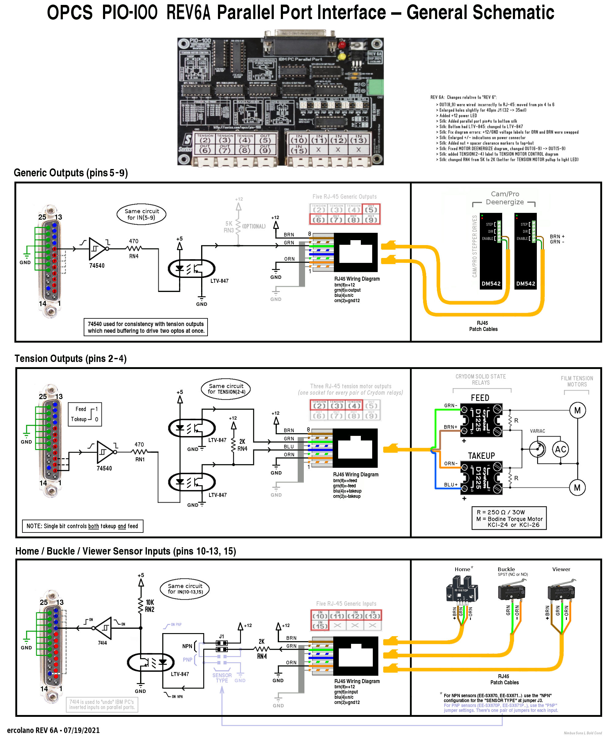
The PIO-100 allows using off-the-shelf cabling in the form of premade DB-25 Male/Male parallel port cables and RJ45 patch cables for clean, easy wiring. Refer to the schematic diagram for how to wire Buckle, Viewer, Home Sensors, etc. with the PIO-100 board. |
Wire up one of the input bits on the parallel port to the buckle, and another one to the viewer.
Note the externally supplied 5VDC supply must be regulated, as this voltage is being supplied directly to the computer's parallel port, and must be TTL compatible.
The viewer switch is typically a SPDT switch; wire the common directly to the input port, and wire the terminals to 5VDC and ground, so that throwing the switch alternates between supply and ground to the common.
The buckle switch is typically a group of SPST 'normally closed' switches wired in series. Any one switch will open to cause a buckle. In this case, you would ground the last switch, and drive the input with the first switch, with an appropriate pull up resistor to ensure when any switch opens, 5VDC is fed to the input.
Based on this example, where the viewer is wired to pin 11, and the buckles are wired to pin 10, the opcsdefs.opc file's buckle and viewer commands would be configured to monitor the port/bit-mask on the parallel port, eg:
    buckle c 0378 40 40
    viewer c 0378 80 80
You may need to zero the bit-mask (i.e. change the last value in the line to 00)
for correct operation.