Com Key 416 "4A" Communication System
-------------------------------------
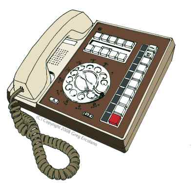 A Com Key 416 Rotary "Satellite" Station
Model 981
* * * * * * * * *
NOTE: The following information is available from http://seriss.com/erco/comkey416/.
The info was compiled from several sources by Greg Ercolano, and is provided AS IS.
Not responsible for errors. For authoritative information on Com Key 416 systems,
refer to the original Bell System documentation. The following information may be
republished in part or in whole, provided 1) this attribution/disclaimer remain
intact and un-edited, and 2) the above URL be provided.
* * * * * * * * *
The Com Key 416 ("4A Communication System") was released by AT&T circa 1975
as an alternative to the older 1A2 phone systems. The Com Key system
has all the control functions (normally found in separate KSU boxes) in
the phone sets themselves. As such, the Com Key 416 systems are referred
to as "KSU-less" systems.
Com Key 416 systems consist of at least one "Primary" set, and one or more
"Satellite" sets. The Primary sets are slightly larger than the Satellite
sets because they house control circuitry common to the rest of the system.
The Primary sets also have an AC cord, to supply power to the control
circuitry, and the power supply that powers the Satellite sets over the
standard 25 pair cables. Both Primary and Satellite station sets have
Amphenol-type 25 pair (50 pin) male ended cables (similar to the modern
"RJ21" style connectors and cabling used for networking)
Several features that were complicated options on the older 1A2 systems
come standard with Com Key 416 systems, such as programmable ringing,
DSS, voice announcements, conferencing, and intercom.
Com Key 416 Features
--------------------
Some of the notable features of this system:
* Master set has all the control circuitry built in; no KSU box needed.
* Call Holding (put a call on hold, so one can either answer another
call, or move to another phone to take the call there, or use the
intercom/page to tell someone else to pick up the call..)
* 2 path intercom with voice or tone signaling:
1) Pick up handset
2) Select an idle ICM button
3) Press one of the white DSS buttons (center of phone)
to signal one of the other stations
* Multiline conferencing. Two or more phone lines can be conferenced
by jamming down two or more of the line buttons simultaneously.
* Built in loud speaker can be enabled by toggling the SPKR button,
top button on row of line buttons. This allows others in the room
to hear both sides of the conversation.
* Auto-release of line buttons (ABR - Auto Button Release).
As soon as the handset is returned, any line buttons down
will pop up. This is to prevent accidentally lifting the receiver
on an active line.
* Recall: similar to 'flash'; a way to flash the line without
loosing the call to access PBX/CO features.
* Ringing is completely programmable: each set can ring
on all lines, one line, or no lines.
* Privacy release: a way to allow other stations to pick up
the same line if the station is programmed for 'privacy'
Com Key 416 Technical Info
--------------------------
The systems are somewhat "user programmable"; switches under the hinged
faceplate on the DSS keys can be set by the user to control which CO lines
cause the phone to ring, and also sets the phone's DSS key number. This,
as opposed to the older 1A2 systems where a telco field engineer would
have to configure such features with extra hardware and punch block
configurations.
A notable internal feature of the Com Key 416 phones is their modular
design; just about everything inside the phone is a 'module' that can be
removed and replaced separately, many can be removed without tools. All
modules are connected to an interconnect board (located under the DSS
keys) with easy to remove connectors, which simplifies servicing and
debugging.
The interconnect board also houses user-modifiable jumpers to access
various factory features that can be changed when add-on hardware kits
are installed or removed.
To access the interconnect board, one can pry up the metal face plate,
and remove the snap-in DSS key module under which the interconnect board
is located. Both the DSS key module and dial pad/rotary dial modules can
be completely removed without tools by novel 'snap in' locks.
Com Key 416 systems required at least one "Primary" or 'master' phone
which can manage up to 2 Central Office (CO) lines, and provides a single
intercom path. Off this master phone, multiple "Satellite" phones can be
connected by standard 25 pair cables.
A second "Primary" phone can be added to the system to add two more CO
lines for a total of four lines and two intercom paths. Satellite phones
also support a single 'private line' each.
The "Primary" sets house the line control circuits that manage the functions
common to all the "Satellite" phones, and have an AC power cord that require
a grounded outlet. The Satellite phones are dependent on the "Primary" sets
for most of the system's features and power.
The Primary sets are physically larger than the Satellite sets; it has a
larger base which houses the AC power supply and numerous control circuits
and relays not found in the Satellite phones. The Satellite phones are
smaller and do not need any AC power; they get their power from the Primary
sets over the 25 pair cables.
Like 1A2 systems, on power failure one can still dial out, and calls in
progress over the CO lines are unaffected. This is due to the fact the
mechanical line buttons physically connect you to the CO lines, and these
connections are unaffected by a power failure. Only the visual (lamps)
and audible (ringing) signaling features would be disabled, as well as
intercom, hold, and other such features. This means incoming calls will
not ring (unless separate ringers are provided that run off the CO's ring
current) Options are available for power-fail ringing, which would
automatically be switched in when the power fails, and switched out when
power is restored.
A typical system involves at least a Primary set, zero or more Satellite
sets, and a 91A or 91B "connecting block" which interfaces the Primary
set to the CO lines, and any number of optional Satellite sets (see
"Technical Limits" below).
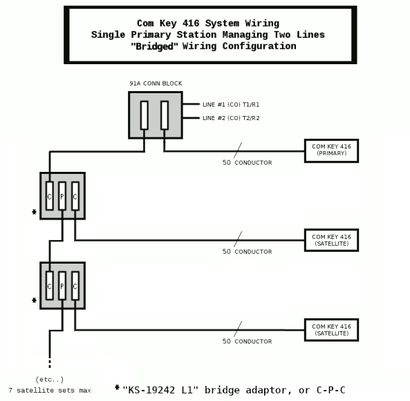
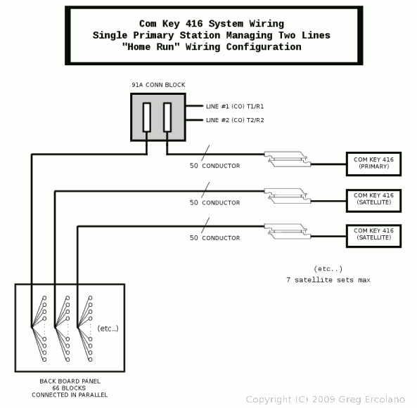
Two common ways to wire a Com Key system; "Bridged" using C-P-C blocks,
or "Home Run" using 66 blocks to span out to the satellites:
A Com Key 416 Rotary "Satellite" Station
Model 981
* * * * * * * * *
NOTE: The following information is available from http://seriss.com/erco/comkey416/.
The info was compiled from several sources by Greg Ercolano, and is provided AS IS.
Not responsible for errors. For authoritative information on Com Key 416 systems,
refer to the original Bell System documentation. The following information may be
republished in part or in whole, provided 1) this attribution/disclaimer remain
intact and un-edited, and 2) the above URL be provided.
* * * * * * * * *
The Com Key 416 ("4A Communication System") was released by AT&T circa 1975
as an alternative to the older 1A2 phone systems. The Com Key system
has all the control functions (normally found in separate KSU boxes) in
the phone sets themselves. As such, the Com Key 416 systems are referred
to as "KSU-less" systems.
Com Key 416 systems consist of at least one "Primary" set, and one or more
"Satellite" sets. The Primary sets are slightly larger than the Satellite
sets because they house control circuitry common to the rest of the system.
The Primary sets also have an AC cord, to supply power to the control
circuitry, and the power supply that powers the Satellite sets over the
standard 25 pair cables. Both Primary and Satellite station sets have
Amphenol-type 25 pair (50 pin) male ended cables (similar to the modern
"RJ21" style connectors and cabling used for networking)
Several features that were complicated options on the older 1A2 systems
come standard with Com Key 416 systems, such as programmable ringing,
DSS, voice announcements, conferencing, and intercom.
Com Key 416 Features
--------------------
Some of the notable features of this system:
* Master set has all the control circuitry built in; no KSU box needed.
* Call Holding (put a call on hold, so one can either answer another
call, or move to another phone to take the call there, or use the
intercom/page to tell someone else to pick up the call..)
* 2 path intercom with voice or tone signaling:
1) Pick up handset
2) Select an idle ICM button
3) Press one of the white DSS buttons (center of phone)
to signal one of the other stations
* Multiline conferencing. Two or more phone lines can be conferenced
by jamming down two or more of the line buttons simultaneously.
* Built in loud speaker can be enabled by toggling the SPKR button,
top button on row of line buttons. This allows others in the room
to hear both sides of the conversation.
* Auto-release of line buttons (ABR - Auto Button Release).
As soon as the handset is returned, any line buttons down
will pop up. This is to prevent accidentally lifting the receiver
on an active line.
* Recall: similar to 'flash'; a way to flash the line without
loosing the call to access PBX/CO features.
* Ringing is completely programmable: each set can ring
on all lines, one line, or no lines.
* Privacy release: a way to allow other stations to pick up
the same line if the station is programmed for 'privacy'
Com Key 416 Technical Info
--------------------------
The systems are somewhat "user programmable"; switches under the hinged
faceplate on the DSS keys can be set by the user to control which CO lines
cause the phone to ring, and also sets the phone's DSS key number. This,
as opposed to the older 1A2 systems where a telco field engineer would
have to configure such features with extra hardware and punch block
configurations.
A notable internal feature of the Com Key 416 phones is their modular
design; just about everything inside the phone is a 'module' that can be
removed and replaced separately, many can be removed without tools. All
modules are connected to an interconnect board (located under the DSS
keys) with easy to remove connectors, which simplifies servicing and
debugging.
The interconnect board also houses user-modifiable jumpers to access
various factory features that can be changed when add-on hardware kits
are installed or removed.
To access the interconnect board, one can pry up the metal face plate,
and remove the snap-in DSS key module under which the interconnect board
is located. Both the DSS key module and dial pad/rotary dial modules can
be completely removed without tools by novel 'snap in' locks.
Com Key 416 systems required at least one "Primary" or 'master' phone
which can manage up to 2 Central Office (CO) lines, and provides a single
intercom path. Off this master phone, multiple "Satellite" phones can be
connected by standard 25 pair cables.
A second "Primary" phone can be added to the system to add two more CO
lines for a total of four lines and two intercom paths. Satellite phones
also support a single 'private line' each.
The "Primary" sets house the line control circuits that manage the functions
common to all the "Satellite" phones, and have an AC power cord that require
a grounded outlet. The Satellite phones are dependent on the "Primary" sets
for most of the system's features and power.
The Primary sets are physically larger than the Satellite sets; it has a
larger base which houses the AC power supply and numerous control circuits
and relays not found in the Satellite phones. The Satellite phones are
smaller and do not need any AC power; they get their power from the Primary
sets over the 25 pair cables.
Like 1A2 systems, on power failure one can still dial out, and calls in
progress over the CO lines are unaffected. This is due to the fact the
mechanical line buttons physically connect you to the CO lines, and these
connections are unaffected by a power failure. Only the visual (lamps)
and audible (ringing) signaling features would be disabled, as well as
intercom, hold, and other such features. This means incoming calls will
not ring (unless separate ringers are provided that run off the CO's ring
current) Options are available for power-fail ringing, which would
automatically be switched in when the power fails, and switched out when
power is restored.
A typical system involves at least a Primary set, zero or more Satellite
sets, and a 91A or 91B "connecting block" which interfaces the Primary
set to the CO lines, and any number of optional Satellite sets (see
"Technical Limits" below).
Two common ways to wire a Com Key system; "Bridged" using C-P-C blocks,
or "Home Run" using 66 blocks to span out to the satellites:
The 91B connecting block is a simple circuit board with a single RJ-11
connector to interface the two CO lines with the master and satellite sets.
It also has two (50) pin amphenol style connectors; the Female connector
is intended to run to the male end of the Primary set's station cable,
and a Male connector intended to either:
* Extend to a chain of C-P-C blocks for the Satellite sets in a
Bridged configuration, or..
* Extend to a back board of interconnected 66 blocks creating a
'star' or 'home run' distribution for the Satellite sets.
Wiring
------
Setting up a phone system was just a matter of attaching the CO lines
to the "91B" block, a 7 foot 25 pair cable between the 91B and the
Primary station, and a 25 pair from the 91B out to the Satellite station(s).
If you don't have a 91A or 91B connection block, you can attach to the
telco lines directly to the primary set:
* Connect CO's Line#1 T/R pair to pins 24+49 (brn/vio + vio/brn) respectively.
* Connect CO's Line#2 T/R pair to pins 25+50 (slt-vio + vio-slt) respectively.
If the primary set is internally configured for Line1&2, the two CO lines
will appear on the first two buttons above the Hold key.
If the primary set is internally configured for Line3&4, the two CO lines
will appear on the 3rd and 4th buttons above the Hold key.
(WARNING: Do NOT wire "1A2 style" to 1+26: that's wrong for Com Key.)
Wiring to the Satellite phones can either be a "Home Run" (ie. "Star") wiring,
or "Bridged" (ie. "Daisy Chained"), or combos of both. "Bridged" configuations
are easiest to configure for the novice, and use the least amount of cable.
Such configurations are made possible by C-P-C blocks, or "bridging adaptors".
These are basically "Y" splitters for the 50 pin amphenols. These allow a single
50 pin connector from the master to be split into two; one for the satellite phone,
and one for the continuing run. (See BSP III 518-450-106 2.10)
Specifically, the "KS-19252 L1" bridging adapters are best
for this, as they can all be interconnected with M/F ended cables, also known as
B25A in the Bell System documentation. (See "KS-19252" below in the TERMINOLOGY section)
All station set cables are male ended, and should mate with a female
cable that runs to the back board or 91B block.
Typical Amphenol Male / Female cables mated
Programming Features
--------------------
There are two places to "program" the phone:
A) The cover between the top and bottom rows of DSS buttons
covers the switches that configure the phone's DSS number
and ring programming
B) Under the metal face plate (you have to pry it up),
you can remove the entire DSS button pad by snapping it out,
revealing an jumper box for various other features of the phone.
See below for details.
Some features can be programmed at the 66 blocks, but the intention
is for most features to be programmed in the phone sets.
Some optional features (paging, music on hold..) involve separate hardware.
Technical Limits
----------------
The recommended technical limits of the system are 2 Primary sets,
14 satellite sets, two intercom paths, 10 DSS paths, and 4 CO lines.
Each primary can support up to 7 satellite sets. Since the Primary sets
are phones too, a total of 16 phone sets can be used. (BSP III 518-450-106
2.08 and 518-450-105 2.01) There is an absolute maximum cabling limit
of 2000 feet total. With a maximum of 16 stations, the limit of cable
length between satellites to both primary stations is 400 feet. (BSP III
518-450-106 3.15)
Com Key 416 -- Bell System Model Numbers
----------------------------------------
There are at least two series of Com Key 416 phones;
the 830/2830 series (BSP III 518-450-105), and the newer, more
common 980/2980 series (BSP III 518-450-106).
The most common to encounter are the 980/2980 series, which
can be identified by having the green LED lamps mounted to the
left side of the line buttons, as opposed to the lamps being
part of the buttons.
Both series are intercompatible with each other, but the newer
series supplied more features.
830/2830 Series
---------------
This is the older 830/2830 series, which have the lamps mounted
inside the line/intercom buttons.
******* Rotary Dial ****** ****** Touch-Tone Dial *****
Model Description Model Description
-------- ------------------- --------- --------------------
836AM-50 "Primary" Station 2836AM-50 "Primary" Station
837AM-50 "Satellite" Station 2837AM-50 "Satellite" Station
The model numbers were often followed by letter/number codes
to define particular features, such as wall mounting vs. desk sets.
(Reference: BSP III 518-450-105 "Ordering Guide")
980/2980 Series
---------------
This later series, which seems to be more commonly encountered,
has the lamps to the left of the buttons.
This series is compatible and interchangeable with the older
830/2830 series.
******* Rotary Dial ****** ****** Touch-Tone Dial *****
Model Description Model Description
------ ------------------- ------- --------------------
981A01 "Primary" Desk Station 2981A01 "Primary" Desk Station
981A02 "Satellite" Desk Station 2981A02 "Satellite" Desk Station
983A03 "Satellite" Desk with BIS 2983A03 "Satellite" Desk with BIS
983A02 "Satellite" Desk with HFAI 2983A02 "Satellite" Desk with HFAI
(Reference: BSP III 518-450-106 2.10)
Com Key 416 Buttons
-------------------
The DSS keys, from left-to-right, top-to-bottom, the keys are:
_____ _____ _____ _____ _____
| 1 | 3 | 5 | 7 | 9 |
|_____|_____|_____|_____|_____|
_____ _____ _____ _____ _____
| 2 | 4 | 6 | 8 | 10 |
|_____|_____|_____|_____|_____|
Between the two rows of buttons is a pop-up cover that contains
white switches that set how the phone rings, and the phone's
DSS code:
_ _ 1 3 5 7 9 _ _
|_| |_| _____________________________ | | | |
1 | | 2 | | |__|__________________________| 3 |_| 4 |_|
|_| |_| off 2 4 6 8 10 |_| |_|
\___________/ \_____________________________/ \___________/
| | |
"Common Audible" DSS Intercom "Common Audible"
Switches for Code Selector Switches for
Line 1 + 2 Line 3 + 4
(shown "on") (shown "off")
The "Common Audible" switches select whether this phone should
ring when Line 1/2/3/4 are ringing. eg. if switches "1" and "2"
are turned on, and "3" and "4" are off, then the phone will only
ring when a call comes into Line 1 or Line 2. The phone will be
silent when calls arrive on Line 3 or Line 4.
Here's an MP3 of a Com Key 416's ring: comkey-416-ring.mp3
The "DSS Intercom Code Selector" sets which DSS key this phone
will respond to. If set to "off", the phone will not be on anyone's
DSS keys. When set to eg. "7", this phone will respond when
anyone presses and holds DSS button #7 and begins speaking;
their voice will be transmitted through the loud speaker in the
phone.
The vertical row of line buttons at the right of the phone are,
from top to bottom:
Spkr - Speaker button
Prv Rls - "Privacy Release"
ICM-2 - Intercom #2
ICM-1 - Intercom #1
Personal Line - unused, unless this option is provided
Line 4
Line 3
Line 2
Line 1
Hold
These are mechanical buttons; when Hold is pressed and released, or
when the handset is placed on hook, any Line buttons or ICM buttons
that were down are released. It is possible to press and hold several
Line buttons down together to form a conference call. Similarly, both
ICM buttons can be held down together to conference two intercom calls
together. You can NOT conference between ICM and Line buttons; the
mechanics of the buttons prevent this. Hold and Prv Rls are both momentary
switches, Spkr is a toggle button.
At the lower-left, the "R" button is a momentary button that flashes the hook,
as a way of notifying the PBX operator.
At the lower-right, a volume knob numbered 1 through 10 controls the speaker
volume, when the SPKR button is locked down.
Com Key 416 Pin Out
-------------------
The pinouts for the Primary and Satellite sets are similar, except for
pins 23-25 and 48-50.
* * * P R I M A R Y S E T * * *
BSP BSP
Pin Color Code Description Pin Color Code Description
_ --- ------- ----- ------------------- --- ------- ----- ------------- _
| 1 blu-wht R(1) "Ring" 26 wht-blu T(1) "Tip" |
LINE 1 | 2 orn-wht CA1 Common Audible 1 27 wht-orn A(1) A lead |
|_ 3 grn-wht LP(1) Lamp 28 wht-grn LC(1) Lamp Common |
_ |
| 4 brn-wht R(2) "Ring" 29 wht-brn T(2) "Tip" | Com Key
LINE 2 | 5 slt-wht CA2 Common Audible 2 30 wht-slt A(2) A lead | "Internal"
|_ 6 blu-red LP(2) Lamp 31 red-blu LC(2) Lamp Common | signal paths
_ | for line 1-4
| 7 orn-red R(3) "Ring" 32 red-orn T(3) "Tip" |
LINE 3 | 8 grn-red CA3 Common Audible 3 33 red-grn A(3) A lead |
|_ 9 brn-red LP(3) Lamp 34 red-brn LC(3) Lamp Common |
_ |
| 10 slt-red R(4) "Ring" 35 red-slt T(4) "Tip" |
LINE 4 | 11 blu-blk CA4 Common Audible 4 36 blk-blu A(4) A lead |
|_ 12 orn-blk LP(4) Lamp 37 blk-orn LC(4) Lamp Common _|
13 grn-blk ICR1 Intercom#1 "Ring" 38 blk-grn ICT1 Intercom#1 "Tip"
14 brn-blk DSS1 DSS Button #1 39 blk-brn DSS2 DSS Button #2
15 slt-blk LCI1 Lamp Common Intercom#1 40 blk-slt LPI1 Lamp Intercom #1
16 blu-yel ICR2 Intercom#2 "Ring" 41 yel-blu ICT2 Intercom#2 "Tip"
17 orn-yel DSS3 DSS Button #3 42 yel-orn DSS4 DSS Button #4
18 grn-yel LCI2 Lamp Common Intercom#2 43 yel-grn LPI2 Lamp Intercom #2
19 brn-yel DSS5 DSS Button #5 44 yel-brn DSS6 DSS Button #6
20 slt-yel COM Power Supply Common 45 yel-slt +V Power Supply +
21 blu-vio DSS7 DSS Button #7 46 vio-blu DSS8 DSS Button #8
22 orn-vio DSS9 DSS Button #9 47 vio-orn DSS10 DSS Button #10
_ 23 grn-vio MOH Music On Hold 48 vio-grn MOH Music On Hold _
CONNECT | 24 brn-vio R1/R3 CO "Ring" line 1 (or 3) 49 vio-brn T1/T3 CO "Tip" line 1 (or 3) | CONNECT
TO CO |_ 25 slt-vio R2/R4 CO "Ring" line 2 (or 4) 50 vio-slt T2/T4 CO "Tip" line 2 (or 4) _| TO CO
** WARNING: When connecting primary set to CO telco lines: use 24/49 and 25/50 pairs. **
** DO NOT attach the CO lines "1A2 style" to e.g. 1/26. Even though AT+T labels **
** 1/26 as T(1)/R(1) in the Com Key manual, these are Com Key's internal voice paths, **
** and should not to be connected directly to the CO lines. (If you make this mistake, **
** it'll "kinda work": you'll see lights and get dialtone, but Hold/Ring won't work.) **
** The naming difference between T(1) vs. T1 is subtle; the former are internal voice **
** paths, the latter are the actual CO lines. **
* * * S A T E L L I T E S E T * * *
BSP BSP
Pin Color Code Description Pin Color Code Description
_ --- ------- ----- ------------------- --- ------- ----- ------------- _
| 1 blu-wht R(1) "Ring" 26 wht-blu T(1) "Tip" |
LINE 1 | 2 orn-wht CA1 Common Audible 1 27 wht-orn A(1) A lead |
|_ 3 grn-wht LP(1) Lamp 28 wht-grn LC(1) Lamp Common |
_ |
| 4 brn-wht R(2) "Ring" 29 wht-brn T(2) "Tip" | Com Key
LINE 2 | 5 slt-wht CA2 Common Audible 2 30 wht-slt A(2) A lead | "Internal"
|_ 6 blu-red LP(2) Lamp 31 red-blu LC(2) Lamp Common | signal paths
_ | for line 1-4
| 7 orn-red R(3) "Ring" 32 red-orn T(3) "Tip" |
LINE 3 | 8 grn-red CA3 Common Audible 3 33 red-grn A(3) A lead |
|_ 9 brn-red LP(3) Lamp 34 red-brn LC(3) Lamp Common |
_ |
| 10 slt-red R(4) "Ring" 35 red-slt T(4) "Tip" |
LINE 4 | 11 blu-blk CA4 Common Audible 4 36 blk-blu A(4) A lead |
|_ 12 orn-blk LP(4) Lamp 37 blk-orn LC(4) Lamp Common _|
13 grn-blk ICR1 Intercom#1 "Ring" 38 blk-grn ICT1 Intercom#1 "Tip"
14 brn-blk DSS1 DSS Button #1 39 blk-brn DSS2 DSS Button #2
15 slt-blk LCI1 Lamp Common Intercom#1 40 blk-slt LPI1 Lamp Intercom #1
16 blu-yel ICR2 Intercom#2 "Ring" 41 yel-blu ICT2 Intercom#2 "Tip"
17 orn-yel DSS3 DSS Button #3 42 yel-orn DSS4 DSS Button #4
18 grn-yel LCI2 Lamp Common Intercom#2 43 yel-grn LPI2 Lamp Intercom #2
19 brn-yel DSS5 DSS Button #5 44 yel-brn DSS6 DSS Button #6
20 slt-yel COM Power Supply Common 45 yel-slt +V Power Supply +
21 blu-vio DSS7 DSS Button #7 46 vio-blu DSS8 DSS Button #8
22 orn-vio DSS9 DSS Button #9 47 vio-orn DSS10 DSS Button #10
23 grn-vio COM Power Supply Common 48 vio-grn V+ Power Supply +
24 brn-vio COM Power Supply Common 49 vio-brn V+ Power Supply +
25 slt-vio COM Power Supply Common 50 vio-slt V+ Power Supply +
WARNING: Although the Com Key 416 phones use regular 25 pair connectors,
and have many pins in common with 1A2, 1A2 and Com Key phones do not share
compatible signals.
For instance, on 1A2 systems it's common to use the yel-slt / slt-yel pair
for 90 volt ringing. On Com Key systems, this pair are V+ and COM respectively;
a 1A2 ring voltage applied to that pair on any Com Key set would be bad.
Com Key 416 Related Terminology: Acronyms and Abbreviations
-----------------------------------------------------------
ABR - Automatic Button Restoration.
Unlike the older 1A2 systems, when a line button is down on a Com Key
416 set, when the user hangs up the phone, the button pops up.
Presumably this is to prevent one from accidentally picking up on
someone else's call in progress; with the older 1A2 systems, when you
finished a call by hanging up, the line button you were using would
remain down. If that line later came in use by someone else, and
during their call you simply picked up the handset without first
selecting an available line, you'd pick up on the other person's
call-in-progress.
The Com Key system seems to prevent this in two ways; by mechanically
popping up all keys that are down when the handset is cradled (hung up),
and also the privacy release feature would seem to prevent accidental
(or intentional) "eves dropping" on calls in progress, unless the
person using the line has hit "Privacy Release" to allow others to
join the call.
B25A - The Bell System part number for an amphenol cable with M/F ends,
which can be used in Com Key to chain all 3-way bridging adapters
(KS-19252 L1, C-P-C) together. See KS-19252 (below) for a wiring
example where only B25A cable is needed to connect up all the
Com Key sets.
BIS - Built In Speaker phone.
This allows two-way conversation without using the handset.
This is different from the "Built In Loudspeker" feature, which
only allows monitoring of the conversation in progress, and not
a two-way conversation.
BSP - Bell System Practices
The BSP manuals are a collection of technical documents and addendum
that describe the various phone systems the Bell System provided,
including block schematics, and recommended configurations and procedures.
There are three volumes; I, II and III.
Referenced here is Volume III, which is the only one of the three volumes
that covered Com Key 416 and 718 phone systems.
C-P-C - Connector-Plug-Connector, or F-M-F (Female/Male/Female)
Refers to the sex of the 3 connectors in a "KS-19252 L1"
3-way splitter for amphenol connectors.
These are the best type of 3-way splitter (or Bridging Adapter)
to use with Com Key.
C-C-C - Connector-Connector-Connector, or F-F-F (Female/Female/Female)
Refers to the sex of the 3 connectors in a "KS-19252 L4"
3-way splitter for amphenol connectors.
Shouldn't be needed for Com Key sets.
CO - Central Office
These are the raw POTS (Plain Old Telephone Service) lines that
come in from the phone company (central office), each line a single
pair of "Tip" and "Ring".
DSS - Direct Station Selection.
The 'DSS keys" are the 10 white buttons along the top of the phone,
which allow one to directly signal one of the other phones in the
system by voice.
Each phone in the system can be assigned to one of the 10 DSS buttons
via the 10 position slider switch located under the plastic "COM KEY"
cover located between the two rows of DSS buttons.
The position of this slider switch identifies that phone's extension
number; so if the switch is set to '5', then anyone in the office
pushing DSS button #5 will voice contact that phone. Normally one
just pushes and holds the DSS button, and if a short tone is heard,
one can begin speaking, their voice will be transmitted through
the called phone's speaker. If the called phone has a "Do Not Distrurb"
feature, the caller will hear a steady tone when the DSS button
is pressed.
With only one Primary phone located on the system, there is only one
intercom line available. When there are two Primary phones, two intercom
lines are available.
If a DSS button is held down, one can voice-signal the called party
through the called party's speaker. Holding down several DSS keys
could signal multiple phones at once. There is also a paging option,
such that one of the 10 DSS keys could be assigned to paging speakers.
HFAI - Hands Free Answer on Intercom
KS-19252 - AT&T part number for a 3 way amphenol bridging adapters.
(See 461-200-102 for info on these adapters)
There's an "L" suffix appended to that number to indicate the sex
of the 3 connectors using "P"lug and "C"onnector terminology
("P"lug is Male, "C"onnector is Female):
Male/
Suffix 3 Connectors inside Female Notes
------ ------------------- ------ ------------------------------------
L1 C - P - C F/M/F Recommended for Com Key using B25A cables
L2 P - C - P M/F/M -
L3 P - P - P M/M/M -
L4 C - C - C F/F/F -
L5 P - C - P M/F/M (Special wiring; see 461-200-102)
The 'L1' (C-P-C) works best for Com Key setups, since they can be
used at each satellite set to chain all the satellites together
to the primary using B25a cables (which have M/F ends). e.g.
B25A cable
________________________________________________
__|________ __|_____
| | _ _ | | | _ |
| | || || | | <-- "KS-19252 L1" bridge adapter | | || | | <-- 91A connection block
| |C||P||C| | (C-P-C) | |P||C| |
| | || || | | | | || | |------ \__ to CO/telco
| |_||_||_| | | |_||_| |------ /
|_____|__|__| |_____|__|
| |______________(Satellite Set #1) |__________(Primary Set)
|
B25A cable |
__|
|
__|________
| | _ _ |
| | || || | | <-- "KS-19252 L1" bridge adapter
| |C||P||C| | (C-P-C)
| | || || | |
| |_||_||_| |
|_____|__|__|
| |______________(Satellite Set #2)
|
B25A cable |
__|
|
__|________
| | _ _ |
| | || || | | <-- "KS-19252 L1" bridge adapter
| |C||P||C| | (C-P-C)
| | || || | |
| |_||_||_| |
|_____|__|__|
| |______________(Satellite Set #3..)
|
..etc..
For more info on wiring Com Key Primary and Satellite sets using bridging
adapters, see BSP 518-450-105, Fig 3 "Typical Installation, Using Bridging
Adapters and Connecting Blocks".
MOH - Music On Hold.
When someone is put on hold, an audio source such as a radio station
or tape player can be supplied via the MOH path.
P-P-P - Plug-Plug-Plug
Refers to the sex of the 3 connectors in a "KS-19252 L3"
3-way splitter (or "bridging adapater) for amphenol connectors.
Shouldn't be needed for Com Key sets.
P-C-P - Plug-Connector-Plug
Refers to the sex of the 3 connectors in a "KS-19252 L2"
3-way splitter (or "bridging adapater) for amphenol connectors.
Shouldn't be needed for Com Key sets.
POTS - Plain Old Telephone Service
The normal phone line service from the phone company, similar to what you
find in homes; a line pair ("Tip" and "Ring") that are normally at
around 48 volts DC when idle, and has a approx. a 90 VAC ring voltage
riding on top of that during ringing, and when the phone is picked up,
the voltage drops to around 6 to 18 VDC when a conversation is in
progress. When the far caller hangs up, most modern central offices
send a CPC (Calling Party Control) signal, which is basically just
a brief open circuit across Tip and Ring. This signal is used by
phone equipment, such as when someone left on Hold abandons the call;
the phone equipment knows to free up the line from Hold. Voice mail
and answering machines use the CPC to prevent recording silence.
You can usually hear CPC by picking up the phone and just listening
to the dialtone.. at some point the CO times out, and interrupts
the dial tone with CPC, followed by a recording that the phone is
off the hook.
PRIV RLS - Privacy Release.
This is a momentary push button below the SPKR button, second button
down from the top in the vertical row of push buttons at the right
of the phone.
R - Recall button
Similar to a 'hook flash', pressing this button is a way of signalling
the PBX operator.
RJ21 - Registered Jack 21 -- the 50 pin "Amphenol" connectors used by this
phone system. The phone company used these connectors on most of their
multiline equipment. The cables have 25 wire pairs (50 conductors total)
using a standard 25 pair color code for wiring.
Female printed circuit board mountable "press fit" versions of this
connector are available from Digikey as part# A24390-ND
(as of this writing, Jan 2015 and updated Jan 2017).
The connectors themselves are physically similar and plug-compatible
to 50 pin SCSI connectors, differing in the connector locking technique;
the phone company's connectors use screws to lock the connectors together,
SCSI used a wire spring snap technique.
SPKR - Speaker button
When this button is locked down, the speaker is engaged, so that both
sides of the conversation can be heard through the speaker.
On BIS Satellite sets and HFAI sets equipped with a 4a speakerphone,
this button is inoperative.
-- [END] --
TODO: o Describe how to configure primary sets:
a) For Line1/2 vs Line3/4 using internal connector
b) To swap polarity of lines using internal connector
c) To verify "SYS"/"SUPP" connector is properly configured
o Adjust table to show actual voltage levels in place of V+ (eg. 24VDC)
o Circuit description. Try tracing eg. line one 24/49 from CO into the
Com Key primary to see what route it takes through the circuit
to get out on 1/26.
o Details about the primary set (power supply, logic board, photos)
(C) Copyright 2008 Greg Ercolano.
If you encounter errors in this document, please report them to: erco@seriss.com
REV 0 - 08/30/08 - Initial Document
REV A - 01/04/23 - Fix Schematics: DSS5