Motor Wiring / Recommended Hardware Engineering

Most of these practices are only recommended engineering practices, not gospel.

Optical Printer Motors

Camera
And
Projector

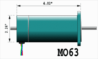
  • Use Superior Electric M0-63 or NEMA23 stepper motors for the camera/projector movements. M0-92 can also work.

  • It's recommended to use double shafted motors (shaft comes out both ends) to facilitate inching knobs/home sensor mounting.

  • Home sensors like Omron photo-microsensors should be on all shutter axes (eg. camera, projector(s) and fader) and mounted out of harms away.

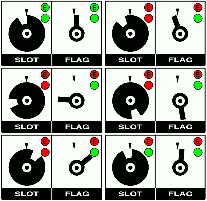
  • 'Rotating flags' or 'slotted disks' may be used to interrupt the home sensors. Just don't make slots or flags too thin; see below.

  • Braid the wires coming off the motors, so they don't fray.

  • Film Loading is best accomplished by programming the OPCS load command to:

    1. Move the projector to the load postion
    2. Deenergize tension motors
    3. Wait for a key
    4. Re-energize tension motors
    5. Move projector back to the seated position

  • Interlock knobs can be found on old printers, and used to manually disengage drive shafts to allow manual manipulation.

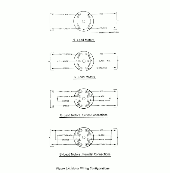
  • It's best to use 4-pin or 6-pin XLR connectors between stepper motor and stepper drive cables. While there's no "standard wiring" for XLR connectors for stepper motors, I can suggest:

      4 Wire Motor
      Red/Yel/Grn/Blu

      4 Wire "Stepper Online" Motor
      Red/Blu/Grn/Blk

             Motor   XLR   Motor    FMD2740C
             Color   Pin#  Cable     Drive
             ─────   ────  ─────    ────────
              Red     1     Red        A+
              Blu     2     Blk        B+
              Grn     3     Grn        A-
              Yel     4     Wht        B-
             Motor   XLR   Motor    DM-542
             Color   Pin#  Cable    Drive
             ─────   ────  ─────    ──────
              Red     1     Red       A-   
              Blu     2     Wht       A+   
              Grn     3     Grn       B-   
              Blk     4     Blk       B+
                  FMD2740C
                 Term Block
                   ┏━━━┓
              GND  ┃ O ┃
              VIN+ ┃ O ┃     XLR   MOTOR
                   ┣━━━┫     ───   ─────
               A-  ┃ O ┃ ──► Grn    Grn
               A+  ┃ O ┃ ──► Red    Red
               B-  ┃ O ┃ ──► Wht    Yel
               B+  ┃ O ┃ ──► Blk    Blu
                   ┗━━━┛
      
               (OX1 Wiring 03/17/24)
                   DM542
                 Term Block
                   ┏━━━┓
               GND ┃ O ┃
               V+  ┃ O ┃     XLR   MOTOR
                   ┣━━━┫     ───   ─────
               A+  ┃ O ┃ ──► Wht    Blu
               A-  ┃ O ┃ ──► Red    Red
               B+  ┃ O ┃ ──► Blk    Blk
               B-  ┃ O ┃ ──► Grn    Grn
                   ┗━━━┛
      
       
          The above wiring gives CW rotation when looking at the motor face and shaft
          (as if it were a clock) when the direction bit is +5V, which is "forward"
          on the A800 pulse generator.
      
          "Motor Cable" colors described here are for Belden 8424 and Belden 8489 cable.

Fader

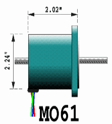
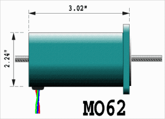
Use anything from an MO61 to an MO63 to control the fader.

Often motorizing an optical printer's fader is the hardest axis to engineer. Some folks rebuild the entire assembly, some folks just mount a motor to the fader dial. Good luck.

For optimal results, gear the fader such that it swings from open to closed in 2 to 3 rotations of the motor shaft.

Mount home sensors such that it triggers at or near the closed position.

You will need to mount the sensor somewhere where it only triggers once during the entire travel of the fader. (If you mount the sensor on the motor shaft, you'll get two or three triggers throughout the full travel of the fader, which is not very useful)

FYI, the OPCS software has the ability to customize home sensing so that, once home is found, the motor can be moved an additional known distance to the actual 'closed' position. This means the sensor does not have to be positioned at exactly closed, if that makes your life easier.

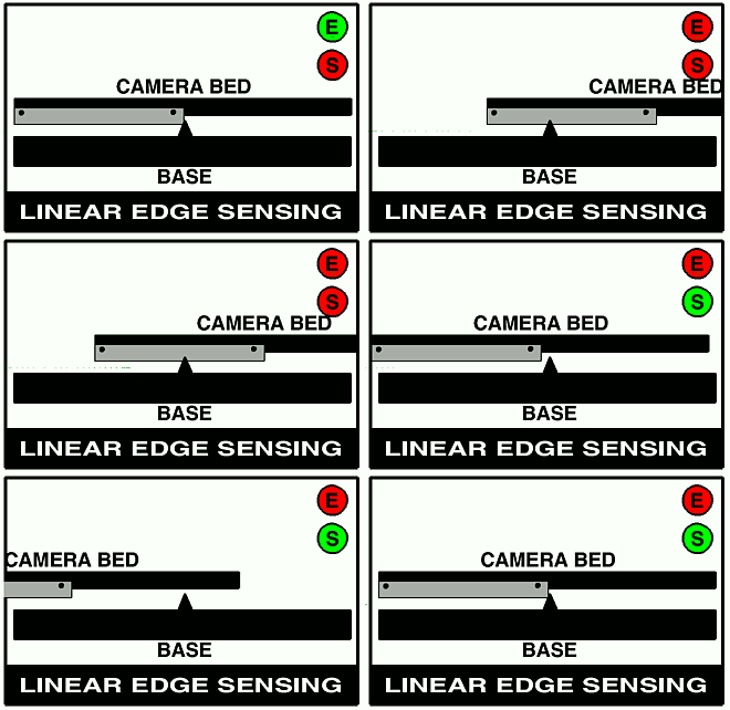
If your fader involves sensing linear motion, see the section on mounting home sensors to detect linear positions.

It is best to use TTL voltage level home sensors, such as the Omron PhotoMicrosensors.

Rotational Positioning Home Sensors

Linear Positioning Home Sensors

Trip Switches

Braiding Motor Wires

Superior Electric Motors

Superior Electric steppers are the most common motors you'll see used on Optical Printers. Here are the most common models..

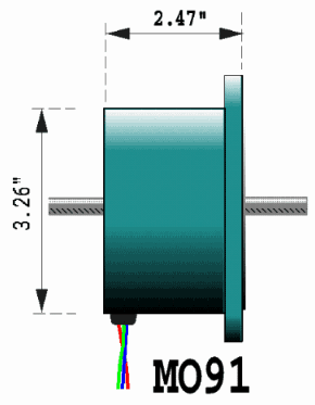
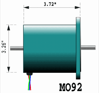
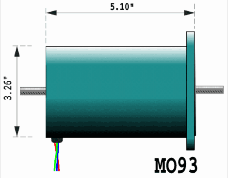
The first digit indicates diameter, the MO-6x's are small, and the MO-9x's are large.

The second digit indicates length:

  • MO61 means 'single stack'
  • MO62 means 'double stack'
  • MO63 means 'triple stack'
The same goes for the MO9x series, but the sizes are larger. Typically, the motors used are:

Typical Motor Applications


Minimum
Size

Maximum
Size

Camera
Projectors

MO63 MO92

Fader

MO62 MO63

Pan/Zoom
Light

MO62 MO91

Pan/Zoom
Heavy

MO63 MO93

Color Wheel

MO61 MO63

Please note: OPCS does not sell motors.
Customers must purchase motors from motion control distributors or motor manufacturers; see the links page.

Superior Electric Motors - Models/Sizes
Superior
MO61
MO62
MO63
Superior
MO91
MO92
MO93

Please note: OPCS does not sell motors.
Customers must purchase motors from motion control distributors or motor manufacturers; see the links page.


© Copyright 1997, Greg Ercolano. All rights reserved. To report documentation errors, send email to